i-ACTIVSENSE


i-ACTIVSENSE (Some Models)
i-ACTIVSENSE is a collective term covering a series of advanced safety and driver support systems which make use of a Forward Sensing Camera (FSC) and radar sensors. These systems consist of active safety and pre-crash safety systems.
These systems are designed to assist the driver in safer driving by reducing the load on the driver and helping to avert collisions or reduce their severity. However, because each system has its limitations, always drive carefully and do not rely solely on the systems.
Active Safety Technology
Active Safety Technology supports safer driving by helping the driver to recognize potential hazards and avert accidents.
Driver awareness support systems
Nighttime visibility
Left/right side and rear side detection
Road sign recognition
Inter-vehicle distance recognition
Driver fatigue detection
Rear obstruction detection when leaving a parking space
Full-surround recognition
Driver support systems
Inter-vehicle distance
Lane departure
Canceling Operation of Blind Spot Monitoring (BSM)
The BSM system can be set to inoperable.
Refer to the Settings section in the Mazda Connect Owner's Manual.
When the BSM is set to inoperable, the BSM and Rear Cross Traffic Alert (RCTA) systems are turned off and the BSM OFF indicator light in the instrument cluster turns on.

When the ignition is switched OFF, the system status before it was turned off is maintained. For example, if the ignition is switched OFF while the BSM and Rear Cross Traffic Alert (RCTA) systems are operational, the BSM and Rear Cross Traffic Alert (RCTA) systems remain operational the next time the ignition is switched ON.


Stop Hold Control
While in headway control using the MRCC with Stop & Go function system, your vehicle will stop when a vehicle ahead stops. When the vehicle is stopped and the stop hold control operates, the MRCC with Stop & Go function indicator light turns on.

-
If the MRCC with Stop & Go function system is canceled during stop hold control, the vehicle is held in its stopped position. The stop hold control can be canceled by performing one the following actions.
-
Press the accelerator pedal and resume driving the vehicle.
-
While forcefully depressing the brake, switch the MRCC with Stop & Go function system off.
-
-
The parking brake is automatically applied and the vehicle is held in its stopped position when 10 minutes have elapsed since the stop hold control operated. At this time, the MRCC with Stop & Go function system is canceled.
-
The brake lights turn on during stop hold control.
To resume driving
After the vehicle ahead starts moving while your vehicle is stopped under stop hold control, press the RES switch or depress the accelerator pedal to cancel the stop hold control and resume driving.
-
When you resume driving by pressing the RES switch, your vehicle does not start moving until the distance between your vehicle and the vehicle ahead lengthens to the specified distance or farther.
-
If the MRCC with Stop & Go function is temporarily canceled during stop hold control, you cannot resume driving by pressing the RES switch when there are no vehicles in front of your vehicle. Depress the accelerator pedal and resume driving the vehicle.
-
If the vehicle ahead starts moving within 3 seconds after your vehicle is stopped by the stop hold control, headway control will resume even if you do not resume driving your vehicle, such as by depressing the accelerator pedal.
Resume driving information
If you do not resume driving within a few seconds after the vehicle ahead starts moving, the multi-information display vehicle-ahead indication flashes to urge the driver to resume driving.
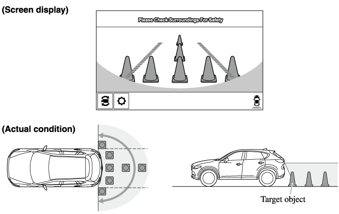
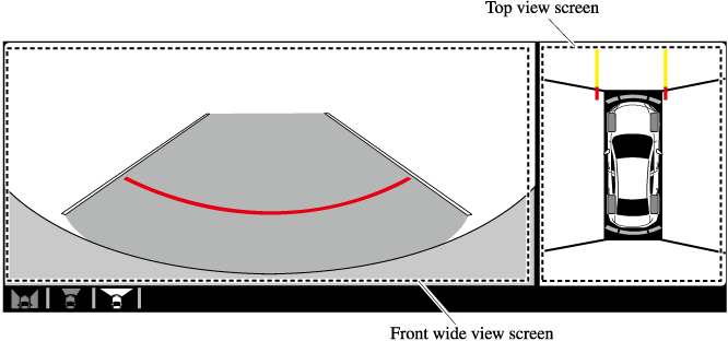
Front Wide View
Use the front wide view to assist in checking the safety of the surrounding area when accelerating from a stop or entering a T-shaped intersection and intersection.
Display range
Viewing the screen
|
Display/Icon |
Content |
|
|---|---|---|
 |
Extended vehicle width lines and distance guide lines (red/blue) |
Indicates the approximate width of the vehicle and the distance (from front end of bumper) in front of the vehicle.
|
-
The parking sensor obstruction detection indication does not display. Switch the screen display to the top view/front view or side view display if the parking sensor warning sound is activated.
-
The front wide view screen displays the image in front of the vehicle at a wide angle and corrects the image to help detect approaching obstructions from the side. Therefore, it differs from the actual view.
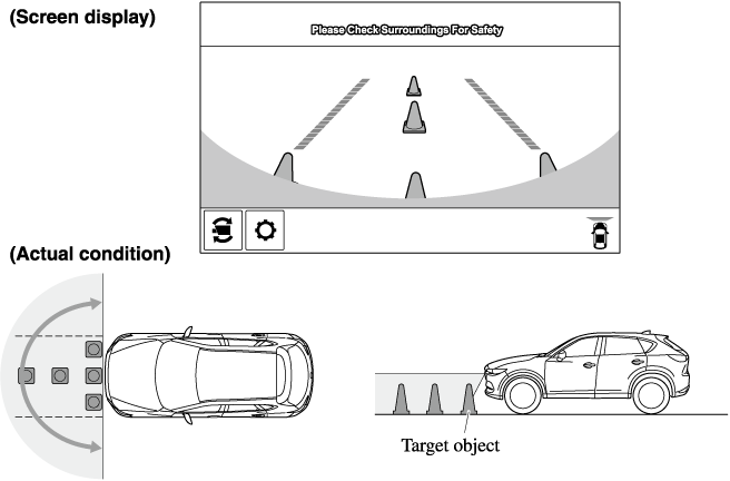
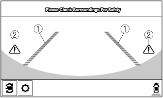
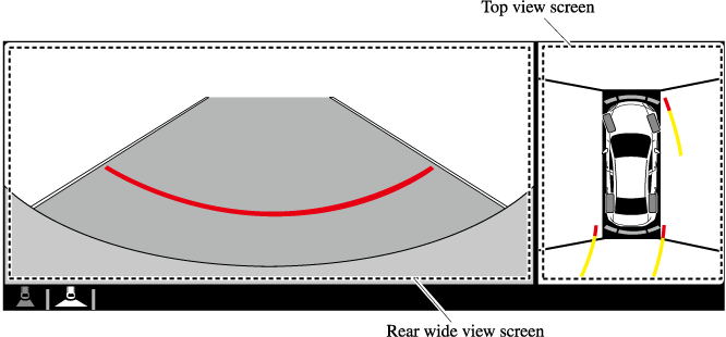
Rear Wide View
Use the rear wide view to assist in checking the safety of the surrounding area when accelerating from a stop, parking, or stopping the vehicle.
Range of displayed screen image
Viewing the screen
|
Display/Icon |
Content |
|
|---|---|---|
|
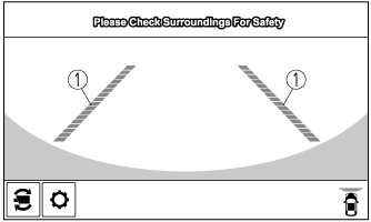
Extended vehicle width lines and distance guide lines (red/blue) |
These guide lines indicate the approximate width of the vehicle and distance to a point measured from the rear of the vehicle (from the end of the bumper).
|
 |
Blind Spot Monitoring (BSM) warning lights |
Indicates when the Rear Cross Traffic Alert (RCTA) has operated. For details, refer to Rear Cross Traffic Alert (RCTA). Refer to Rear Cross Traffic Alert (RCTA) (Search). |
-
The parking sensor obstruction detection indication does not display. Switch the screen display to the top view/rear view display if the parking sensor warning sound is activated.
-
The rear wide view screen displays the image at the rear of the vehicle at a wide angle and corrects the image to help detect approaching obstructions from the side. Therefore, it differs from the actual view.
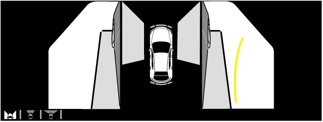
360° View Monitor (Mazda Connect (Type B)) (Some Models)
Types of Images Displayed on the Screen
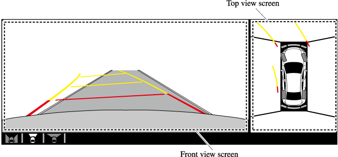
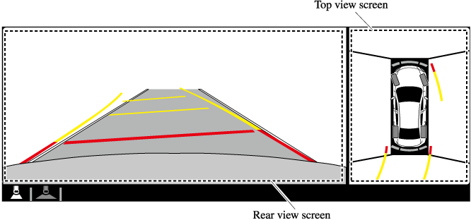
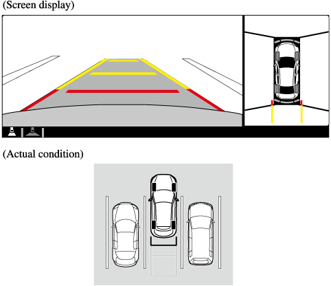
Top View/Rear View
Use the top view/rear view to assist in checking the safety of the surrounding area when accelerating from a stop, parking, or stopping the vehicle.
Range of displayed screen image

-
In the top view screen, the areas in black at the front and rear of the vehicle image and the seams where each of the camera images merge are blind spots.
-
Because images displayed in the top view screen are processed from each camera, the top view screen may display in the following ways.
-
If an image containing an object with a conspicuous color is picked up by any of the cameras, the screen area for each camera may be affected and it may display in that color.
-
Obstructions displayed in the rear view may not display on the top view screen.
-
If the position or angle of each camera changes due to tilting of the vehicle, the image may appear distorted.
-
Lines on the road may appear distorted at the seams where each of the camera images merge.
-
The screen area for each camera may appear bright/dark depending on the illumination level around any of the cameras.
-
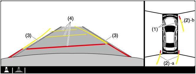
Viewing the screen
|
Display/Icon |
Content |
|
|---|---|---|
|
(1) |
Tire icon |
Indicates the tire direction. Moves in conjunction with the steering wheel operation. |
|
(2) |
Projected vehicle path lines (yellow & red) |
Indicates the approximate projected path of the vehicle. Moves in conjunction with the steering wheel operation. a) Indicates the path where the edge of the rear bumper is expected to travel. b) Indicates the path where the outer side of the vehicle is expected to travel. |
|
(3) |
Extended vehicle width lines (blue) |
These guide lines indicate the approximate width of the vehicle. |
|
(4) |
Projected vehicle path distance guide lines (yellow & red) |
These guide lines indicate the approximate distance to a point measured from the rear of the vehicle (from the end of the bumper).
|
The setting can be changed so that the projected vehicle path lines are not displayed.
Refer to the Settings section in the Mazda Connect Owner's Manual.
How to use the projected vehicle path line function
-
The front of the vehicle swings out wide when turning the steering wheel while reversing. Maintain sufficient distance between the vehicle and an obstruction.
-
The parking sensor detection range has limitations. For example, obstructions closing in from the side and objects short in height may not be detected. Always confirm the safety around the vehicle visually when driving.
For details, refer to the parking sensor obstruction detection indication and warning sound.
Refer to Parking Sensor System (Search).
-
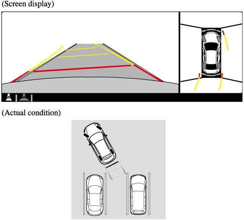
Because there might be a difference between the image displayed on the screen, such as indicated in the following, and the actual conditions when parking, always check the safety at the rear of the vehicle and the surrounding area directly with your eyes.
-
Even though the back end of the parking space (or garage) displayed on the screen and distance guide lines appear parallel, they may not actually be parallel.
-
When parking in a space with a division line on only one side of the parking space, even though the division line and the vehicle width guide line appear parallel, they may not actually be parallel.
-
-
The following shows an example of vehicle parking with the steering wheel turned to the left while backing up the vehicle. When backing into a parking space from the opposite direction, the steering operation is reversed.
-
Back the vehicle into the parking space by turning the steering wheel so that the vehicle enters the center of the parking space.
-
After the vehicle starts entering the parking space, stop and adjust the steering wheel so that the distance between the vehicle width lines and the sides of the parking space on the left and right are roughly equal, and then continue backing up slowly.
-
Once the vehicle width lines and the sides of the parking space on the left and right are parallel, straighten the wheels and back the vehicle slowly into the parking space. Continue checking the vehicle's surroundings and then stop the vehicle in the best possible position. (If the parking space has division lines, check whether the vehicle width guide lines are parallel to them.)