


i-ACTIVSENSE
i-ACTIVSENSE
Active Safety Technology
Active Safety Technology supports safer driving by helping the driver to recognize potential hazards and avert accidents.
Driver awareness support systems
Nighttime visibility
Left/right side and rear side detection
Road sign recognition
Inter-vehicle distance recognition
Front obstruction detection when approaching a crosswalk
Rear obstruction detection when leaving a parking space
Full-surround recognition
Driver fatigue detection
Driver support systems
Inter-vehicle distance
Lane departure
Lane keeping
Inter-vehicle distance and lane keeping
Pre-Crash Safety Technology
Pre-crash safety technology is designed to assist the driver in averting collisions or reducing their severity in situations where they cannot be avoided.
Collision damage reduction
Front Side Radar Sensor
Your vehicle is equipped with front side radar sensor.

-
Front side radar sensor
The following systems also use the front side radar sensor.
-
Front Cross Traffic Alert (FCTA)
The front side radar sensor function by detecting the radio waves reflected off a vehicle approaching from the front or an obstruction sent from the radar sensor.
Heed the following precautions to assure correct operation of each system.
-
Always keep the surface of the front bumper near the front side radar sensors clean so that they operate normally. Also, do not apply items such as stickers.
Refer to Exterior Care (Search).
-
If the front bumper receives a severe impact, the system may no longer operate normally. Stop the system immediately and have the vehicle inspected at an Authorized Mazda Dealer.
-
Vehicles are shipped with the direction of the front side radar sensor adjusted for each vehicle to a loaded vehicle condition so that the front side radar sensor detect approaching vehicles correctly. If the direction of the front side radar sensor has deviated for some reason, have the vehicle inspected at an Authorized Mazda Dealer.
-
For repairs or replacement of the front side radar sensor, or bumper repairs, paintwork, and replacement near the radar sensors, consult an Authorized Mazda Dealer.


The radar sensors are regulated by the relevant radio wave laws of the country in which the vehicle is driven. If the vehicle is driven abroad, authorization from the country in which the vehicle is driven may be required.
When any of the following conditions is met, the detection ability of the front side radar sensors may decrease and each system may not operate normally.
-
Under bad weather conditions (rain, fog, and snow).
-
The front bumper around a front side radar sensor is deformed.
-
Foreign matter (such as ice, snow, and mud) is adhering to the front bumper around a front side radar sensor.
The front side radar sensors may not detect the following target objects.
-
Small motorcycles
-
Bicycles
-
Pedestrians
-
Animals
-
Shopping carts
-
Stationary objects on the road or roadside
-
Vehicles with shapes that may not reflect radar waves (such as unloaded trailers with low vehicle heights and sports cars).
Rear Side Radar Sensor
Your vehicle is equipped with rear side radar sensor.

-
Rear side radar sensor
The following systems also use the rear side radar sensor.
-
Blind Spot Monitoring (BSM)
-
Rear Cross Traffic Alert (RCTA)
-
Smart Brake Support (SBS) reverse drive detection
-
Emergency Lane Keeping (ELK)
The rear side radar sensors emit radio waves and detect the radio waves reflected off a vehicle approaching from the rear or an obstruction.
Heed the following precautions to assure correct operation of each system.
-
Always keep the surface of the rear bumper near the rear side radar sensors clean so that they operate normally. Also, do not apply items such as stickers.
Refer to Exterior Care (Search).
-
If the rear bumper receives a severe impact, the system may no longer operate normally. Stop the system immediately and have the vehicle inspected at an Authorized Mazda Dealer.
-
Vehicles are shipped with the direction of the rear side radar sensor adjusted for each vehicle to a loaded vehicle condition so that the rear side radar sensor detect approaching vehicles correctly. If the direction of the rear side radar sensor has deviated for some reason, have the vehicle inspected at an Authorized Mazda Dealer.
-
For repairs or replacement of the rear side radar sensor, or bumper repairs, paintwork, and replacement near the radar sensors, consult an Authorized Mazda Dealer.
The radar sensors are regulated by the relevant radio wave laws of the country in which the vehicle is driven. If the vehicle is driven abroad, authorization from the country in which the vehicle is driven may be required.
When any of the following conditions is met, the detection ability of the rear side radar sensors may decrease and each system may not operate normally.
-
Under bad weather conditions (rain, fog, and snow).
-
The rear bumper around a rear side radar sensor is deformed.
-
Foreign matter (such as ice, snow, and mud) is adhering to the rear bumper around a rear side radar sensor.
The rear side radar sensors may not detect the following target objects.
-
Small motorcycles
-
Bicycles
-
Pedestrians
-
Animals
-
Shopping carts
-
Stationary objects on the road or roadside
-
Vehicles with shapes that may not reflect radar waves (such as unloaded trailers with low vehicle heights and sports cars).
Front Camera/Side Cameras/Rear Camera
Your vehicle is equipped with a front camera, side cameras, and a rear camera.

-
Side cameras
-
Front camera
-
Rear camera
Each camera is used by the following system.
-
360°View Monitor
The front camera, side cameras, and rear camera shoot images of the area surrounding the vehicle.
Adaptive Front Lighting System (AFS)
The adaptive front lighting system (AFS) automatically adjusts the headlight beams to the left or right in conjunction with the operation of the steering wheel after the headlights have been turned on and the vehicle speed is about 2 km/h (2 mph) or higher.
A system malfunction or operation conditions are indicated by a warning.
Refer to Exterior Light Warning Indication/Warning Light (Search).
The Adaptive Front Lighting System (AFS) can be switched to on/off using the personalization function.
Refer to the Settings section in the Mazda Connect Owner's Manual.
Lane Departure Warning


Blind Spot Monitoring (BSM)
The BSM is designed to assist the driver in checking the area to the rear of the vehicle on both sides during lane changes by notifying the driver of the presence of vehicles approaching from the rear in an adjacent lane.
BSM operation
The BSM detects vehicles approaching from the rear while traveling in the forward direction at a speed of 10 km/h (6.3 mph) or faster and notifies the driver by turning on the BSM warning indicator light and displaying the vehicle detection screen.
If the turn signal lever is operated to signal a turn in the direction in which the BSM warning indicator light is illuminated while the approaching vehicle is detected, the BSM notifies the driver of possible danger flashing on the BSM warning indicator light, and by activating the warning sound and the warning screen indicator display.
The detection area on this system covers the driving lanes on both sides of the vehicle and from the rear part of the front doors to about 50 m (164 ft) behind the vehicle.

-
Your vehicle
-
Detection areas
Always check the surrounding area visually before making an actual lane change:
The system is only designed to assist you in checking for vehicles at your rear when making a lane change. Due to certain limitations with the operation of this system, the BSM warning indicator light, the warning sound and the warning screen indicator display may not activate or they might be delayed even though a vehicle is in an adjacent driving lane. Always make it your responsibility as a driver to check the rear.
-
The BSM will operate when all of the following conditions are met:
-
The power switch is switched ON.
-
The i-ACTIVSENSE warning indication/warning light in the instrument cluster is turned off.
-
The vehicle speed is about 10 km/h (6.3 mph) or faster.
-
-
The BSM will not operate under the following circumstances.
-
The vehicle speed falls below about 10 km/h (6.3 mph) even though the i-ACTIVSENSE warning indication/warning light is turned off.
-
The selector lever is shifted to reverse (R) and the vehicle is reversing.
-
The turning radius is small (making a sharp turn, turning at intersections).
-
-
In the following cases, the i-ACTIVSENSE warning indication/warning light turns on and operation of the system is stopped. If the i-ACTIVSENSE warning indication/warning light remains illuminated, have the vehicle inspected at an Authorized Mazda Dealer as soon as possible.
-
Some problem with the system including the BSM warning indicator lights is detected.
-
A large deviation in the installation position of a rear side radar sensor on the vehicle has occurred.
-
There is a large accumulation of snow or ice on the rear bumper near a rear side radar sensor. Remove any snow, ice or mud on the rear bumper.
-
Driving on snow-covered roads for long periods.
-
The temperature near the rear side radar sensor becomes extremely hot due to driving for long periods on slopes during the summer.
-
The lead-acid battery voltage has decreased.
-
-
Under the following conditions, the rear side radar sensor cannot detect target objects or it may be difficult to detect them.
-
The rear bumper around the rear side radar sensor is deformed.
-
Radio wave interference from a radar sensor equipped on a nearby vehicle.
-
The approaching vehicle is any of the following shapes.
-
The size of the vehicle body is extremely small.
-
The vehicle height is extremely low or high.
-
A special type of vehicle with a complex shape.
-
-
A vehicle is in the detection area at the rear in an adjacent driving lane but it does not approach. The BSM determines the condition based on radar detection data.
-
A vehicle is traveling alongside your vehicle at nearly the same speed for an extended period of time.
-
Vehicles approaching in the opposite direction.
-
A vehicle in an adjacent driving lane is attempting to pass your vehicle.
-
A vehicle is in an adjacent lane on a road with extremely wide driving lanes. The detection area of the rear side radar sensor is set at the road width of expressways.
-
-
In the following case, the flashing of the BSM warning indicator light, and the activation of the warning sound and the warning screen indicator display may not occur or they may be delayed.
-
A vehicle makes a lane change from a driving lane two lanes over to an adjacent lane.
-
Driving on steep slopes.
-
Crossing the summit of a hill or mountain pass.
-
When there is a difference in the height between your driving lane and the adjacent lane.
-
Directly after the BSM system becomes operable by changing the setting.
-
-
If the road width is extremely narrow, vehicles two lanes over may be detected. The detection area of the rear side radar sensor is set according to the road width of expressways.
-
The BSM warning indicator light may turn on and the vehicle detection screen may be displayed in the display in reaction to stationary objects (guardrails, tunnels, sidewalls, and parked vehicles) on the road or the roadside.
Objects such as guardrails and concrete walls running alongside the vehicle.

Places where the width between guardrails or walls on each side of the vehicle narrows.

The walls at the entrance and exits of tunnels, turnouts.

-
A BSM warning indicator light may flash or the warning beep may be activated several times when making a turn at a city intersection.
-
Turn off the BSM while pulling a trailer or while an accessory such as a bicycle carrier is installed to the rear of the vehicle. Otherwise, the radar’s radio waves will be blocked causing the system to not operate normally.
-
In the following cases, it may be difficult to view the illumination/flashing of the BSM warning indicator lights equipped on the door mirrors.
-
Snow or ice is adhering to the door mirrors.
-
The front door glass is fogged or covered in snow, frost or dirt.
-
-
The rear side radar sensor of the BSM may be regulated under the radio wave related laws of the country where the vehicle is driven. If this system is used abroad, it may be necessary to turn off the system.
Refer to Rear Side Radar Sensor (Search).
-
The system switches to the Rear Cross Traffic Alert (RCTA) function when the selector lever is shifted to the reverse (R) position.
Refer to Rear Cross Traffic Alert (RCTA) (Search).
Canceling Operation of Blind Spot Monitoring (BSM)
The BSM system can be set to inoperable.
-
(If only the BSM is turned off)
Refer to the Settings section in the Mazda Connect Owner's Manual.
-
(If the BSM is turned off by operating the i-ACTIVSENSE OFF switch)
Refer to i-ACTIVSENSE OFF Switch (Search).
If the power switch is switched OFF while you have canceled the system using the i-ACTIVSENSE OFF switch, the system is automatically enabled the next time the power switch is switched ON. However, if the system is canceled using [Settings] in Mazda Connect, the system is not automatically enabled.
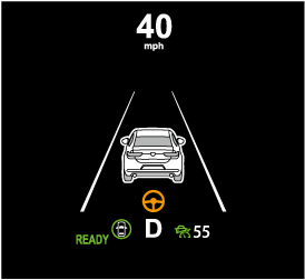
Driver Attention Alert (DAA) Display
When the system detects driver fatigue or decreased attentiveness, it activates the warning sound and displays an alert in the multi-information display.

-
“Time for a Break” message is displayed
Driver Monitoring (DM) (Some Models)
Rear Cross Traffic Alert (RCTA) (Some Models)
Traffic Jam Assist (TJA) (Some Models)
Close Proximity Warning
If your vehicle approaches the vehicle ahead while traveling under headway control using the Traffic Jam Assist (TJA), a warning sound is activated and a brake warning is indicated on the multi-information display. Check the surrounding conditions and keep a safe distance from the vehicle ahead.

-
“Depress Brake Pedal” message is displayed
-
While the accelerator pedal is being depressed, the warnings and brake control do not operate even if your vehicle approaches the vehicle ahead.
-
In the following cases, the warnings and brakes may not operate even if your vehicle approaches the vehicle ahead.
-
Your vehicle is being driven at the same speed as the vehicle ahead.
-
Immediately after the Traffic Jam Assist (TJA) is set.
-
Immediately after the accelerator pedal is released.
-
Another vehicle cuts into the driving lane.
-
Steering Wheel Operation Assist
When the system determines that the vehicle might be deviating from its lane, the steering wheel operation assist operates.
The system notifies the driver that it provided steering wheel operation assistance on the multi-information display and the active driving display.
Multi-information display (Basic display)

Multi-information display (i-ACTIVSENSE display)
Active driving display

-
When the driver operates the steering wheel while the steering wheel operation assist is operating, the steering wheel operation assistance is canceled.
-
When the steering wheel operation assist is performed several times within a certain period of time, the warning sound is activated.
Stopping the Emergency Lane Keeping (ELK) System Operation
The ELK can be set to inoperable.
Refer to the Settings section in the Mazda Connect Owner's Manual.
When the ELK is canceled, the ELK OFF indicator light turns on.

Smart Brake Support (SBS) (Some Models)
Smart Brake Support (SBS)
The SBS is a system designed to detect target objects using sensors and cameras equipped on the vehicle, and to reduce damage in the event of a collision by operating the brake control if there is the possibility of your vehicle colliding with a target object.
One part of the SBS functions when you are driving forward and the other part functions when you are driving in reverse.
Refer to Forward drive detection (Search).
Refer to Reverse drive detection (Search).
Stopping the Smart Brake Support (SBS) System Operation
The SBS can be changed to inoperable.
Refer to the Settings section in the Mazda Connect Owner's Manual.
When the SBS is canceled, the SBS OFF indicator light turns on.

When the power switch is switched OFF while the SBS forward drive detection is canceled, the SBS forward drive detection is automatically enabled the next time the power switch is switched ON.
360° View Monitor (Some Models)
360° View Monitor
The 360° View Monitor consists of the following functions which assist the driver in checking the area surrounding the vehicle using various indications in the center display and a warning sound while the vehicle is being driven at low speeds or while parking.
-
Top view
The top view displays an image of the vehicle from directly above on the center display by combining the images taken from the 4 cameras set on all sides of the vehicle. The top view displays on the right side of the screen when the front view or rear view screen is being displayed. The top view assists the driver in checking the area surrounding the vehicle when the vehicle is moving forward or in reverse.
-
Front view/front wide view
The image from the front of the vehicle is displayed on the center display.
The view from the front assists the driver in checking the front of the vehicle by displaying guide lines on the displayed image taken from the front of the vehicle.
-
Side view
The images taken from the front left and right sides of the vehicle are displayed on the center display.
The side view assists the driver in checking the front sides of the vehicle by displaying guide lines on the displayed image taken from the front left and right sides of the vehicle.
-
Rear view/rear wide view
The image from the rear of the vehicle is displayed on the center display.
The image from the rear assists the driver in checking the rear of the vehicle by displaying guide lines on the displayed image taken from the rear of the vehicle.
-
Parking sensor
If there are any obstructions near the vehicle while the top view/side view is displayed, an obstruction detection indication turns on around the bumper in the center display.
The parking sensors use ultrasonic sensors to detect obstructions around the vehicle when the vehicle is driven at low speeds, such as during garage or parallel parking, and notifies the driver of the approximate distance from the vehicle to the surrounding obstruction using sound and an obstruction detection indication.
Refer to Parking Sensor System (Search).
-
Front Cross Traffic Alert (FCTA)
If there is the possibility of a collision with an approaching vehicle while the front view/front wide view/side view is displayed, a warning is displayed on the center display.
The Front Cross Traffic Alert (FCTA) is designed to assist the driver in checking both sides of the vehicle when the vehicle starts to drive at an intersection.
Refer to Front Cross Traffic Alert (FCTA) (Search).
-
Rear Cross Traffic Alert (RCTA)
If there is the possibility of a collision with an approaching vehicle while the rear view/rear wide view is displayed, a warning is displayed on the center display.
The Rear Cross Traffic Alert (RCTA) uses rear side radar sensor to detect vehicles approaching from the rear left and right sides of the vehicle, and it assists the driver in checking the rear of the vehicle while reversing by flashing the Blind Spot Monitoring (BSM) warning lights and activating the warning sound.
Refer to Rear Cross Traffic Alert (RCTA) (Search).
360° View Monitor Range

-
Cameras
-
Ultrasonic sensors
-
Front/Rear side radar sensors
Always confirm the safety of the area around the vehicle with the mirrors and directly with your eyes when driving:
The 360° View Monitor is an auxiliary device which assists the driver in checking the safety of the area around the vehicle.
The shooting range of the cameras and detection range of the sensors are limited. For example, the areas in black at the front and rear of the vehicle image and the seams where each of the camera images merge are blind spots where an obstruction may not be visible. In addition, the extended vehicle width lines and projected vehicle path lines are only to be used as references, and the images on the screen may differ from the actual conditions.
-
Do not use the 360° View Monitor under any of the following conditions.
-
Icy or snow-covered roads.
-
Tire chains or a temporary spare tire is installed.
-
The front or rear doors are not fully closed.
-
The vehicle is on a road incline.
-
Bumpy roads.
-
The door mirrors are retracted.
-
-
Do not hit the front/rear camera, front bumper, liftgate, and door mirrors forcefully. The camera position or installation angle may shift.
-
The cameras are waterproof. Do not disassemble, modify, or remove a camera.
-
The camera cover is made of hard plastic, therefore do not apply oil film remover, organic solvents, wax, or coating agents. If any such agent gets on the camera cover, wipe it off using a soft cloth immediately.
-
Do not rub the camera lens forcefully, or clean it with an abrasive or hard brush. Otherwise, it could scratch the camera lens and negatively affect the images.
-
If a camera lens is severely damaged by flying gravel, have the camera replaced. For camera replacement, consult an Authorized Mazda Dealer.
-
Consult an Authorized Mazda Dealer for repair, painting, or replacement of the front/rear camera, front bumper, liftgate and door mirrors.
-
Heed the following cautions to assure that the 360° View Monitor operates normally.
-
Do not modify the vehicle suspensions or lower/raise the vehicle body, or both.
-
Always use tires of the specified type and size for the front and rear wheels. Consult an Authorized Mazda Dealer for tire replacement.
-
-
When the display is cold, images may leave trails or the screen might be darker than usual, making it difficult to check the vehicle surroundings. Always confirm the safety at the front and around the vehicle visually when driving.
-
The method for parking/stopping the vehicle using the 360° View Monitor differs depending on the road circumstances/conditions and the vehicle conditions. When and how much you turn the steering wheel will differ depending on the situation, therefore always check the vehicle surroundings directly with your eyes while using the system.
Also, before using the system, always make sure that the vehicle can be parked/stopped in the parking/stopping space.
-
If there are water droplets, snow, or mud on the camera lens, wipe it off using a soft cloth. If the camera lens is especially dirty, wash it off with mild detergent.
-
If the camera lens is touched or there is any dirt on it, it could affect the screen image. Wipe the lens using a soft cloth.
-
If the area where the camera is installed, such as the front bumper, liftgate or door mirrors, has been damaged in a vehicle accident, the camera (position, installation angle) may have shifted. Always consult an Authorized Mazda Dealer to have the vehicle inspected.
-
If the camera is subjected to excessive changes in temperature such as by pouring hot water on the camera during cold weather, the 360° View Monitor may not operate normally.
-
If the vehicle is driven during cold temperatures and the camera temperature decreases, the top view and the side view may become unclear. However, this does not indicate a problem. If the vehicle is stopped for a while and the camera temperature increases, the top view and the side view will return to the normal condition.
-
If the lead-acid battery voltage is low, the screen might be temporarily difficult to view, however, this does not indicate a problem.
-
The 360° View Monitor has limitations. Objects under the bumper or near both ends of the bumper cannot be displayed.
-
Obstructions above the upper image range of the camera are not displayed.
-
Under the following conditions, the screen might be difficult to view, however this does not indicate a problem.
-
The temperature near the lens is high/low.
-
Rainy conditions, water droplets on the camera, or high humidity.
-
Mud or foreign matter near the camera.
-
The area around the vehicle is dark.
-
Extremely bright light such as sunlight or headlights hitting the camera lens directly.
-
The surroundings are illuminated by vehicle lights, fluorescent lights, or LED lights (display may flicker).
-
Extremely small dark or white dots appear on the screen (dots may flicker).
-
An object is close to a camera.
-
-
Because the 360° View Monitor camera uses a special lens, the distance displayed on the screen differs from the actual distance.
-
Obstructions displayed on the screen may appear differently than in actuality. (Obstructions may appear fallen, larger, or longer than they actually are.)
-
Do not apply stickers to a camera or the area around it. In addition, do not install accessories or an illuminated number/character license plate to the area around a camera. Otherwise, the camera may not correctly display the surrounding conditions.
-
Only rear and rear wide images displayed on the monitor from the 360° View Monitor camera are reversed images (mirror images).
-
Free/open source software information
This product includes free/open sources. Information about the licensing and source code is available at the following URL.
Types of Images Displayed on the Screen
Top view/Front view
Displays the image of the area around the vehicle and the vehicle front.

-
Top view screen
-
Front view screen
-
“Check surroundings for safety.” message is displayed
Top view/Front wide view
Displays the image of the area around the vehicle and the front of the vehicle (wide-area).

-
Top view screen
-
Front wide view screen
-
“Check surroundings for safety.” message is displayed
Side view
Displays the image of the left and right sides of the vehicle.

-
Left side view screen
-
Right side view screen
-
“Check surroundings for safety.” message is displayed
Top view/Rear view
Displays the image of the area around the vehicle and the rear of the vehicle.

-
Top view screen
-
Rear view screen
-
“Check surroundings for safety.” message is displayed
Top view/Rear wide view
Displays the image of the area around the vehicle and the rear of the vehicle (wide-area).

-
Top view screen
-
Rear wide view screen
-
“Check surroundings for safety.” message is displayed
Top View/Front View
Use the top view/front view to assist in checking the safety of the surrounding area when accelerating from a stop, parking, or stopping the vehicle.
Display range

-
Target object
-
In the top view screen, the areas in black at the front and rear of the vehicle image and the seams where each of the camera images merge are blind spots.
-
Because images displayed in the top view screen are processed from each camera, the top view screen may display in the following ways.
-
Depending on the surrounding environment, the color of objects may be displayed on the screen in a color different from the actual one.
-
Depending on the surrounding environment, it may take a few seconds for the color of the screen display to adjust.
-
Obstructions displayed in the front view may not display on the top view screen.
-
If the position or angle of each camera changes due to tilting of the vehicle, the image may appear distorted.
-
Lines on the road may appear distorted at the seams where each of the camera images merge.
-
The screen area for each camera may appear bright/dark depending on the illumination level around any of the cameras.
-
Viewing the screen

|
Display/Icon |
Content |
|
|---|---|---|
|
(1) |
Tire icon |
Indicates the tire direction. Moves in conjunction with the steering wheel operation. |
|
(2) |
Projected vehicle path lines (yellow & red) |
Indicates the approximate projected path of the vehicle. Moves in conjunction with the steering wheel operation. a) Indicates the path where the edge of the front bumper is expected to travel. b) Indicates the path where the inner side of the vehicle is expected to travel. |
|
(3) |
Extended vehicle width lines (blue) |
Indicates the approximate width of the vehicle. |
|
(4) |
Projected vehicle path distance guide lines (yellow & red) |
Indicates the distance (from front end of bumper) in front of the vehicle.
|
The parking sensor detection range has limitations. For example, obstructions closing in from the side and objects short in height may not be detected. Always confirm the safety around the vehicle visually when driving.
For details, refer to the parking sensor obstruction detection indication and warning sound.
Refer to Parking Sensor System (Search).
The setting can be changed so that the projected vehicle path lines are not displayed.
Refer to the Settings section in the Mazda Connect Owner's Manual.
How to use the projected vehicle path line function

-
(Screen display)
-
(Actual condition)
Make sure that there are no obstructions within the projected vehicle path lines.
Drive the vehicle forward while turning the steering wheel so that no obstructions come within the projected vehicle path lines.
Top View/Front Wide View

Use the top view/front wide view to assist in checking the safety of the surrounding area when accelerating from a stop or entering a T-shaped intersection and intersection.
Display range

-
Target object
-
In the top view screen, the areas in black at the front and rear of the vehicle image and the seams where each of the camera images merge are blind spots.
-
Because images displayed in the top view screen are processed from each camera, the top view screen may display in the following ways.
-
Depending on the surrounding environment, the color of objects may be displayed on the screen in a color different from the actual one.
-
Depending on the surrounding environment, it may take a few seconds for the color of the screen display to adjust.
-
Obstructions displayed in the front view may not display on the top view screen.
-
If the position or angle of each camera changes due to tilting of the vehicle, the image may appear distorted.
-
Lines on the road may appear distorted at the seams where each of the camera images merge.
-
The screen area for each camera may appear bright/dark depending on the illumination level around any of the cameras.
-
Viewing the screen

|
Display/Icon |
Content |
|
|---|---|---|
|
(1) |
Extended vehicle width lines and distance guide lines (blue & red) |
Indicates the approximate width of the vehicle and the distance (from front end of bumper) in front of the vehicle.
|
The front wide view screen displays the image in front of the vehicle at a wide angle and corrects the image to help detect approaching obstructions from the side. Therefore, it differs from the actual view.
Side View
Use the side view to assist in checking the safety of the surrounding area when accelerating from a stop, parking, or stopping the vehicle.
Display range

-
Target object
Viewing the screen

|
Display/Icon |
Content |
|
|---|---|---|
|
(1) |
Projected vehicle path lines (yellow) |
Indicates the approximate projected path of the vehicle. Moves in conjunction with the steering wheel operation. The projected vehicle path lines (yellow) indicate the path the inner side of the vehicle is expected to travel. |
|
(2) |
Vehicle parallel guide lines (blue) |
Indicates the approximate vehicle width including the door mirrors. |
|
(3) |
Vehicle front end guide lines (blue) |
Indicates the point about 0.25 m (9.84 in) from the front edge of the vehicle (front edge of the bumper). |
The setting can be changed so that the projected vehicle path lines are not displayed.
Refer to the Settings section in the Mazda Connect Owner's Manual.
How to use the projected vehicle path line function

-
(Screen display)
-
(Actual condition)
Make sure that there are no obstructions within the projected vehicle path lines.
Turn the steering wheel so that the projected vehicle path lines travel inside of the obstruction (A), and drive the vehicle forward until it passes the obstruction.
If the projected vehicle path lines are on an obstruction (B) or outside of the obstruction (C), the vehicle may contact the obstruction when turning the vehicle sharply.
-
The parking sensor detection range has limitations. For example, obstructions closing in from the side and objects short in height may not be detected. Always confirm the safety around the vehicle visually when driving.
For details, refer to the parking sensor obstruction detection indication and warning sound.
Refer to Parking Sensor System (Search).
-
Do not turn the steering wheel any more until the vehicle has passed the obstruction, even if the obstruction is not visible on the side view image. If the steering wheel is turned even more, the vehicle may contact the obstruction if it is turned sharply.
-
Because there might be a difference between the image displayed on the screen and the actual conditions, always check the safety of the surrounding area using the mirrors and directly with your eyes when driving.
-
Even though the object displayed on the screen, such as a road curb or a division line of a parking space, and the vehicle parallel guide lines appear parallel, they may not actually be parallel.
Top View/Rear Wide View
Use the top view/rear wide view to assist in checking the safety of the surrounding area when accelerating from a stop, parking, or stopping the vehicle.
Range of displayed screen image

-
Target object
-
In the top view screen, the areas in black at the front and rear of the vehicle image and the seams where each of the camera images merge are blind spots.
-
Because images displayed in the top view screen are processed from each camera, the top view screen may display in the following ways.
-
Depending on the surrounding environment, the color of objects may be displayed on the screen in a color different from the actual one.
-
Depending on the surrounding environment, it may take a few seconds for the color of the screen display to adjust.
-
Obstructions displayed in the front view may not display on the top view screen.
-
If the position or angle of each camera changes due to tilting of the vehicle, the image may appear distorted.
-
Lines on the road may appear distorted at the seams where each of the camera images merge.
-
The screen area for each camera may appear bright/dark depending on the illumination level around any of the cameras.
-
Viewing the screen

|
Display/Icon |
Content |
|
|---|---|---|
|
(1) |
Extended vehicle width lines and distance guide lines (blue & red) |
These guide lines indicate the approximate width of the vehicle and distance to a point measured from the rear of the vehicle (from the end of the bumper).
|
The top view/rear wide view screen displays the image at the rear of the vehicle at a wide angle and corrects the image to help detect approaching obstructions from the side. Therefore, it differs from the actual view.
Margin of Error Between Road Surface on Screen and Actual Road Surface
There might be some margin of error between the road surface appearing on the screen and the actual road surface. A margin of error in the perceived distance could lead to an accident, therefore be aware of the following conditions which can more easily produce errors in the perceived distance.
The vehicle tilts due to weight of passengers and cargo.
If the vehicle is tilted, obstructions picked up by a camera can appear farther or closer than the actual distance from the vehicle.
Front camera

-
Obstruction
-
Margin of error
Side camera

-
Obstruction
-
Margin of error
Rear camera

-
Obstruction
-
Margin of error
There is a steep up or down grade in the road at the front or rear of the vehicle
If there is a steep up or down grade in the road at the front or rear of the vehicle, obstructions picked up by the camera can appear farther or closer than the actual distance from the vehicle.
Front camera

-
Appears further than actual distance
-
Distance of obstruction being viewed on screen
-
Actual distance of obstruction from vehicle
-
Actual obstruction
-
Obstruction appearing on screen
-
Appears closer than actual distance
Side camera

-
Appears further than actual distance
-
Distance of obstruction being viewed on screen
-
Actual distance of obstruction from vehicle
-
Actual obstruction
-
Obstruction appearing on screen
-
Appears closer than actual distance
Rear camera

-
Appears further than actual distance
-
Distance of obstruction being viewed on screen
-
Actual distance of obstruction from vehicle
-
Obstruction appearing on screen
-
Actual obstruction
-
Appears closer than actual distance
If the vehicle is on a slope, obstructions taken by the camera can appear farther or closer than the actual distance from the vehicle.
Three-dimensional object at vehicle front or rear
Because the vehicle front end guide lines (side camera) or the distance guide lines (rear camera) are displayed based on a flat surface, the distance to the three-dimensional object displayed on the screen is different from the actual distance.
Side camera

-
(Screen display)
-
(Actual condition)
Rear camera

-
(Screen display)
-
(Actual condition)
-
Sensed distance on screen A>B>C
-
Actual distance B>C=A
System Problem Indication
|
Center display indication |
Cause |
Action to be taken |
|---|---|---|
|
“No camera signal.” is displayed |
The control unit might be damaged. |
Have your vehicle inspected by an Authorized Mazda Dealer. |
|
Screen is pitch-black and blank |
The camera might be damaged. |
|
