


i-ACTIVSENSE
i-ACTIVSENSE (Some Models)
i-ACTIVSENSE is a collective term covering a series of advanced safety and driver support systems which make use of a Forward Sensing Camera (FSC) and radar sensors. These systems consist of active safety and pre-crash safety systems.
These systems are designed to assist the driver in safer driving by reducing the load on the driver and helping to avert collisions or reduce their severity. However, because each system has its limitations, always drive carefully and do not rely solely on the systems.
Active Safety Technology
Active Safety Technology supports safer driving by helping the driver to recognize potential hazards and avert accidents.
Driver awareness support systems
Nighttime visibility
Left/right side and rear side detection
Road sign recognition
Inter-vehicle distance recognition
Driver fatigue detection
Rear obstruction detection when leaving a parking space
Full-surround recognition
Driver support systems
Inter-vehicle distance
Lane departure
Inter-vehicle distance and lane keeping
Pre-Crash Safety Technology
Pre-crash safety technology is designed to assist the driver in averting collisions or reduce their severity in situations where they cannot be avoided.
Collision damage reduction in low vehicle speed range
Forward driving
Reverse driving
Collision damage reduction in medium/high speed range
Camera and Sensors
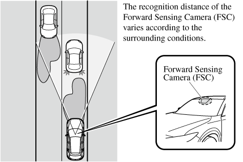
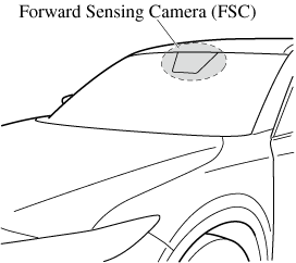
Forward Sensing Camera (FSC)
The Forward Sensing Camera (FSC) detects lane indications and recognizes headlights, taillights and city lights during nighttime driving. In addition, it also detects the vehicle ahead, pedestrians, or obstructions. The following systems also use the Forward Sensing Camera (FSC).
-
High Beam Control System (HBC)
-
Driver Attention Alert (DAA)
-
Lane-keep Assist System (LAS) & Lane Departure Warning System (LDWS)
-
Traffic Jam Assist (TJA)
-
Traffic Sign Recognition System (TSR)
-
Advanced Smart City Brake Support (Advanced SCBS)
-
Smart City Brake Support [Forward] (SCBS F)
-
Smart Brake Support (SBS)
-
Mazda Radar Cruise Control with Stop & Go function (MRCC with Stop & Go function)
The Forward Sensing Camera (FSC) is installed at the top of the windshield near the rearview mirror.
Refer to Forward Sensing Camera (FSC) (Search).
Radar sensor (front)
The radar sensor (front) functions by detecting the radio waves reflected off a vehicle ahead sent from the radar sensor. The following systems also use the radar sensor (front).
-
Mazda Radar Cruise Control with Stop & Go function (MRCC with Stop & Go function)
-
Distance Recognition Support System (DRSS)
-
Traffic Jam Assist (TJA)
-
Smart Brake Support (SBS)
The radar sensor (front) is mounted behind the radiator grille.
Refer to Radar Sensor (Front) (Search).
Radar sensors (rear)
The radar sensors (rear) function by detecting the radio waves reflected off a vehicle approaching from the rear or an obstruction sent from the radar sensors. The following systems also use the radar sensors (rear).
-
Blind Spot Monitoring (BSM)
-
Rear Cross Traffic Alert (RCTA)
The radar sensors (rear) are installed inside the rear bumper, one each on the left and right sides.
Refer to Radar Sensors (Rear) (Search).
Ultrasonic sensors (rear)
The ultrasonic sensors (rear) function by detecting the ultrasonic waves reflected off obstructions at the rear sent from the ultrasonic sensors. The following systems also use the ultrasonic sensors (rear).
-
Smart City Brake Support [Reverse] (SCBS R)
The ultrasonic sensors (rear) are mounted in the rear bumper.
Refer to Ultrasonic Sensors (Rear) (Search).
Front camera/side cameras/rear view camera
The front camera, side cameras, and rear camera shoot images of the area surrounding the vehicle. The 360° View Monitor uses each camera.
Cameras are installed to the front bumper, door mirrors, and liftgate.
Refer to Front Camera/Side Cameras/Rear Camera (Search).
Adaptive Front Lighting System (AFS) (Some Models)
The adaptive front lighting system (AFS) automatically adjusts the headlight beams to the left or right in conjunction with the operation of the steering wheel after the headlights have been turned on.
A system malfunction or operation conditions are indicated by a warning.
Refer to Contact Authorized Mazda Dealer and Have Vehicle Inspected (Search).
The Adaptive Front Lighting System (AFS) function can be switched to operable/inoperable using the personalization function.
Refer to the Settings section in the Mazda Connect Owner's Manual.


High Beam Control System (HBC) (Some Models)
The HBC determines the conditions in front of the vehicle using the Forward Sensing Camera (FSC) while driving in darkness to automatically switch the headlights between high and low beams.
Refer to Forward Sensing Camera (FSC) (Search).
While driving the vehicle at a speed of about 30 km/h (19 mph) or more, the headlights are switched to high beams when there are no vehicles ahead or approaching in the opposite direction.
The system switches the headlights to low beams when one of the following occurs:
-
The system detects a vehicle or the headlights/lights of a vehicle approaching in the opposite direction.
-
The vehicle is driven on roads lined with streetlamps or on roads in well-lit cities and towns.
-
The vehicle is driven at less than about 20 km/h (12 mph).
The warning light turns on when the system has a malfunction.
Refer to Contact Authorized Mazda Dealer and Have Vehicle Inspected (Search).
-
Do not adjust the vehicle height, modify the headlight units, or remove the camera, otherwise the system will not operate normally.
-
Do not rely excessively on the HBC and drive the vehicle while paying sufficient attention to safety. Switch the headlights between the high beams and low beams manually if necessary.
The timing in which the system switches the headlights changes under the following conditions. If the system does not switch the headlights appropriately, manually switch between high and low beams according to the visibility as well as road and traffic conditions.
-
When there are sources of light in the area such as streetlamps, illuminated signboards, and traffic signals.
-
When there are reflective objects in the surrounding area such as reflective plates and signs.
-
When visibility is reduced under rain, snow and foggy conditions.
-
When driving on roads with sharp turn or hilly terrain.
-
When the headlights/rear lamps of vehicles in front of you or in the opposite lane are dim or not illuminated.
-
When there is sufficient darkness such as at dawn or dusk.
-
When the luggage compartment is loaded with heavy objects or the rear passenger seats are occupied.
-
When visibility is reduced due to a vehicle in front of you spraying water from its tires onto your windshield.
Blind Spot Monitoring (BSM) Warning Indicator Light/Display Indicator/Blind Spot Monitoring (BSM) Warning Beep
The BSM or Rear Cross Traffic Alert (RCTA) system notifies the driver of the presence of vehicles in adjacent lanes or at the rear of the vehicle using the BSM warning indicator light, the warning sound and the display indicator (vehicles with instrument cluster (Type A/B) and active driving display) (BSM) while the systems are operational.
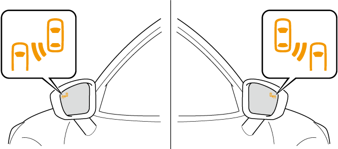
BSM warning indicator lights
The BSM warning indicator lights are equipped on the left and right door mirrors. The warning indicator lights turn on when a vehicle approaching from the rear in an adjacent lane is detected.
When the ignition is switched ON, the warning indicator light turns on momentarily and then turns off after a few seconds.
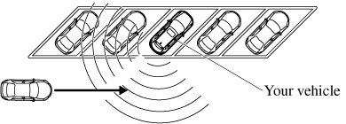
Forward driving (BSM operation)
The BSM detects vehicles approaching from the rear and turns on the BSM warning indicator lights equipped on the door mirrors according to the conditions. Additionally, while a BSM warning indicator light is illuminated, if the turn signal lever is operated to signal a turn in the direction in which the BSM warning indicator light is illuminated, the BSM warning indicator light flashes.
Reverse driving (Rear Cross Traffic Alert (RCTA) system operation)
The Rear Cross Traffic Alert (RCTA) system detects a vehicle approaching from the rear of the vehicle and flashes the BSM warning indicator lights.
Function for cancelling illumination dimmer
If the BSM warning indicator lights turn on when the parking lights are turned on, the brightness of the BSM warning indicator lights is dimmed.
If the BSM warning indicator lights are difficult to see due to glare from surrounding brightness when traveling on snow-covered roads or under foggy conditions, press the dimmer cancellation button to cancel the dimmer and increase the brightness of BSM warning indicator lights when they turn on.
Refer to Dashboard Illumination (Search), (Search), (Search).
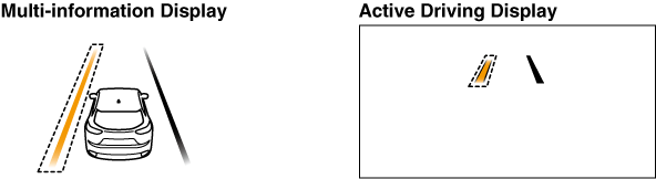
Display indicator (Vehicles with multi-information display and active driving display)
The detected approaching vehicle and warning are displayed in the multi-information display and active driving display when the vehicle is moving forward (BSM operational).
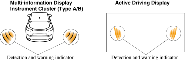
The detected direction is displayed with a detection indicator (white) when an approaching vehicle is detected. In addition, if the turn signal lever is operated to signal a lane change while the vehicle is detected, the display changes the color (amber) of the warning indicator.
BSM warning beep
The BSM warning beep is activated simultaneously with the flashing of a BSM warning indicator light.
Traffic Sign Display Indication
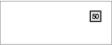
The following traffic signs are displayed on the active driving display.
Speed limit signs
Do not enter signs
Stop signs
Speed limit signs
-
When the vehicle speed is about 1 km/h (0.6 mph) or faster, the speed limit sign is displayed when any one of the following conditions are met.
-
The Forward Sensing Camera (FSC) recognizes a speed limit sign as a sign targeted for your vehicle and the vehicle passes it.
-
The speed limit sign stored in the navigation system is read (if the Forward Sensing Camera (FSC) does not recognize a speed limit sign).
-
-
In the following cases, display of the speed limit sign stops.
-
The Forward Sensing Camera (FSC) recognizes the speed limit sign and the vehicle is driven for a certain distance after passing the sign.
-
Each sensor determines that the vehicle has changed direction of travel.
-
The Forward Sensing Camera (FSC) recognizes a new speed limit sign which differs from the previous one (displays the new speed limit sign).
-
The speed limit sign stored in the navigation system is not read within a certain period of time (if the Forward Sensing Camera (FSC) does not recognize a speed limit sign, the speed limit sign stored in the navigation system is displayed).
-
The vehicle speed exceeds the displayed speed limit sign by 30 km/h (19 mph) or more after a certain period of time has elapsed since the speed limit sign was displayed. (Except when there is information for the speed limit sign in the navigation system)
-
Do not enter signs
-
A do not enter sign is displayed when all of the following conditions are met.
-
The vehicle speed is about 60 km/h (37 mph) or slower.
-
The Forward Sensing Camera (FSC) recognizes a do not enter sign as a sign targeted for your vehicle and the vehicle passes it.
-
-
When the Forward Sensing Camera (FSC) recognizes the do not enter sign and a certain period of time has elapsed since the vehicle passed the sign, display of the do not enter sign stops.
Stop sign
-
A stop sign is displayed when all of the following conditions are met:
-
The vehicle speed is about 30 km/h (19 mph) or slower.
-
The Forward Sensing Camera (FSC) recognizes a stop sign as a sign targeted for your vehicle.
-
-
When a certain period of time has elapsed since the stop sign was displayed, display of the stop sign stops.
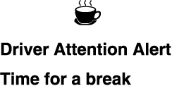
Driver Attention Alert (DAA) Display (White)
When the system detects driver fatigue or decreased attentiveness, it activates the warning sound and displays an alert in the multi-information display.
Canceling Driver Attention Alert (DAA)
The DAA can be set to not activate.
Refer to the Settings section in the Mazda Connect Owner's Manual.
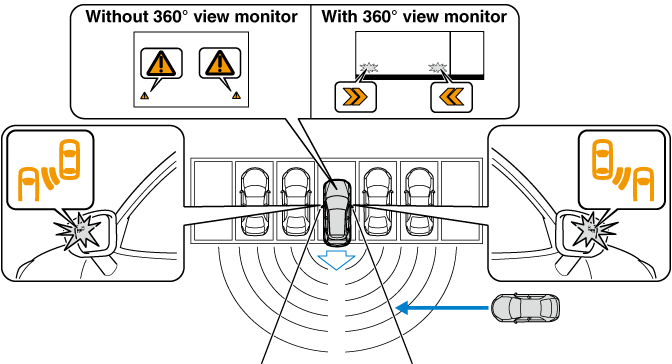
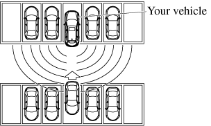
Rear Cross Traffic Alert (RCTA) (Some Models)
The RCTA system is designed to assist the driver in checking the area to the rear of the vehicle on both sides while the vehicle is reversing by alerting the driver to the presence of vehicles approaching the rear of the vehicle.
The RCTA system detects vehicles approaching from the rear left and right sides of the vehicle, and the rear of the vehicle while the vehicle is being reversed out of a parking space, and notifies the driver of possible danger using the Blind Spot Monitoring (BSM) warning indicator lights and the warning buzzer.

RCTA operation
-
The RCTA system operates when the selector lever is shifted to the reverse (R) position.
-
If there is the possibility of a collision with an approaching vehicle, the Blind Spot Monitoring (BSM) warning indicator lights flashes and the warning beep is activated simultaneously.
(With rear view monitor)
The RCTA warning indication in the rearview monitor also synchronizes with the Blind Spot Monitoring (BSM) warning indicator light on the door mirrors.
(With 360° view monitor)
The RCTA warning indication in the 360° view monitor also synchronizes with the Blind Spot Monitoring (BSM) warning indicator light on the door mirrors.
Always check the surrounding area visually before actually putting the vehicle in reverse:
The system is only designed to assist you in checking for vehicles at the rear when putting the vehicle in reverse. Due to certain limitations with the operation of this system, the Blind Spot Monitoring (BSM) warning indicator lights may not flash or it might be delayed even though a vehicle is behind your vehicle. Always make it your responsibility as a driver to check the rear.
-
In the following cases, the Blind Spot Monitoring (BSM) OFF indicator light turns on and operation of the system is stopped. If the Blind Spot Monitoring (BSM) OFF indicator light remains illuminated, have the vehicle inspected at an Authorized Mazda Dealer as soon as possible.
-
Some problem with the system including the Blind Spot Monitoring (BSM) warning indicator lights has occurred.
-
A large deviation in the installation position of a radar sensor (rear) on the vehicle has occurred.
-
There is a large accumulation of snow or ice on the rear bumper near a radar sensor (rear).
-
Driving on snow-covered roads for long periods.
-
The temperature near the radar sensors becomes extremely hot due to driving for long periods on slopes during the summer.
-
The lead-acid battery voltage has decreased.
-
-
Under the following conditions, the radar sensors (rear) cannot detect target objects or it may be difficult to detect them.
-
The vehicle speed when reversing is about 15 km/h (9 mph) or faster.
-
The radar sensor (rear) detection area is obstructed by a nearby wall or parked vehicle. (Reverse the vehicle to a position where the radar sensor detection area is no longer obstructed.)

-
A vehicle is approaching directly from the rear of your vehicle.
-
The vehicle is parked at an angle.
-
Directly after the Blind Spot Monitoring (BSM) system becomes operable using the personalization feature.
-
Radio wave interference from a radar sensor equipped on a nearby parked vehicle.
-
-
In the following cases, it may be difficult to view the illumination/flashing of the Blind Spot Monitoring (BSM) warning indicator lights equipped on the door mirrors.
-
Snow or ice adheres to the door mirrors.
-
The front door glass is fogged or covered in snow, frost or dirt.
-
-
Turn off the RCTA system while pulling a trailer or while an accessory such as a bicycle carrier is installed to the rear of the vehicle. Otherwise, the radio waves emitted by the radar will be blocked causing the system to not operate normally.
Mazda Radar Cruise Control with Stop & Go function (MRCC with Stop & Go function) (Some Models)
The MRCC with Stop & Go function system is designed to maintain headway control*1 with a vehicle ahead according to your vehicle's speed using a radar sensor (front) to detect the distance to the vehicle ahead and a preset vehicle speed without you having to use the accelerator or brake pedals.
-
Headway Control: Control of the distance between your vehicle and the vehicle ahead detected by the Mazda Radar Cruise Control (MRCC) system.
Additionally, if your vehicle starts closing in on the vehicle ahead such as if the vehicle ahead brakes suddenly, a warning sound and a warning indication in the display are activated simultaneously to alert you to maintain a sufficient distance between the vehicles.
If the vehicle ahead stops while you are following behind it, your vehicle will stop and be held stopped automatically (stop hold control), and headway control will resume when you resume driving the vehicle such as by pressing the RES switch.
Also refer to the following before using the MRCC with Stop & Go function.
-
i-stop (Search)
-
AUTOHOLD (Search)
-
Forward Sensing Camera (FSC) (Search)
-
Radar sensor (front) (Search)
Do not rely completely on the MRCC with Stop & Go function:
The MRCC with Stop & Go function system has detection limitations depending on the type of vehicle ahead and its conditions, the weather conditions, and the road conditions. Additionally, the system may be unable to decelerate sufficiently to avoid hitting the vehicle ahead if the vehicle ahead applies the brakes suddenly or another vehicle cuts into the driving lane, which could result in an accident.
Always drive carefully and verify the surrounding conditions and depress the brake pedal or accelerator pedal while keeping a safer distance from vehicles ahead or on-coming vehicles.
Do not use the MRCC with Stop & Go function system in the following locations, using the MRCC with Stop & Go function system at the following locations may result in an unexpected accident:
-
General roads other than highways (Driving under these conditions using the MRCC with Stop & Go function system is not possible.)
-
Roads with sharp curves and where vehicle traffic is heavy and there is insufficient space between vehicles.
-
Roads where frequent and repetitive acceleration and deceleration occur (Driving under these conditions using the MRCC with Stop & Go function system is not possible).
-
When entering and exiting interchanges, service areas, and parking areas of highways (If you exit a highway while headway control is in use, the vehicle ahead will no longer be tracked and your vehicle may accelerate to the set speed).
-
Slippery roads such as ice or snow-bound roads (Tires could spin causing you to lose vehicle control, or the stop hold control may not operate.)
-
Long, descending slopes (to maintain distance between vehicles, the system automatically and continuously applies the brakes which could result in the loss of brake power.)
-
Slopes with a steep gradient (The vehicle ahead may not be detected correctly, your vehicle may slide while stopped by the stop hold control, and it may accelerate suddenly after it starts moving.)
For safety purposes, switch the MRCC with Stop & Go function system off when it is not being used.
Do not get out of the vehicle while the stop hold control is operating:
Getting out of the vehicle while the stop hold control is operating is dangerous as the vehicle may move unexpectedly and result in an accident. Before getting out of the vehicle, switch the MRCC with Stop & Go function system off, shift the selector lever to the P position, and apply the parking brake.
If your vehicle is towed or you are towing something, switch the MRCC with Stop & Go function system off to prevent a mis-operation.
-
The MRCC with Stop & Go function system does not detect the following as physical objects.
-
Vehicles approaching in the opposite direction
-
Pedestrians
-
Stationary objects (stopped vehicles, obstructions)
-
If a vehicle ahead is traveling at an extremely low speed, the system may not detect it correctly.
-
-
During headway control travel, do not set the system for detection of two-wheeled vehicles such as motorcycles and bicycles.
-
Do not use the MRCC with Stop & Go function system under conditions in which close proximity warnings are frequently activated.
-
During headway control travel, the system accelerates and decelerates your vehicle in conjunction with the speed of the vehicle ahead. However, if it is necessary to accelerate for a lane change or if the vehicle ahead brakes suddenly causing you to close in on the vehicle rapidly, accelerate using the accelerator pedal or decelerate using the brake pedal depending on the conditions.
-
While the MRCC with Stop & Go function system is in use, it does not cancel even if the selector lever is operated and any intended engine braking does not occur. If deceleration is required, lower the set speed or depress the brake pedal.
-
The sound of the automatic brakes operating may be heard, however, it does not indicate a problem.
-
The brake lights turn on while the MRCC with Stop & Go function automatic braking is operating.
Setting the System
The MRCC with Stop & Go function system operates when all of the following conditions are met.
-
Vehicle speed is 0 km/h (0 mph) to 145 km/h (90 mph)
-
The MRCC with Stop & Go function is turned on.
-
The brake pedal is not depressed.
-
The parking brake is released (Electric Parking Brake (EPB) indicator light is turned off).
-
There is no problem with the DSC.
-
All the doors are closed.
-
The driver's seat belt is fastened.
-
The selector lever is in the drive (D) position or manual (M) position (manual mode).
-
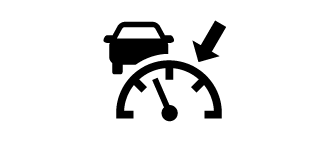
In the following cases, the MRCC with Stop & Go function system is canceled when the vehicle is traveling at 30 km/h (20 mph) or less and “Mazda Radar Cruise Control disabled under 30 km/h (20 mph)” is displayed in the multi-information display.
-
The Forward Sensing Camera (FSC) cannot detect target objects (There is problem with the Forward Sensing Camera (FSC) or windshield is dirty).
-
There is a problem with the stop hold control function.
-
There is a problem with the Electric Parking Brake (EPB).
-
-
It may not be possible to set the MRCC with Stop & Go function system directly after starting the engine, while the DSC operation is being checked.
Turning on the system
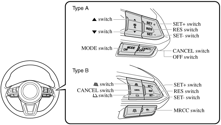
Steering wheel (Type A)
When the MODE switch is pressed once, the MRCC with Stop & Go function system turns on, and the MRCC with Stop & Go function main indication (white) turns on and the vehicle speed and the distance between the vehicles while in headway control can be set.
Steering wheel (Type B)
When the MRCC switch is pressed once, the MRCC with Stop & Go function system turns on, and the MRCC with Stop & Go function main indication (white) turns on and the vehicle speed and the distance between the vehicles while in headway control can be set.
In addition, the MRCC with Stop & Go function system display indication is displayed on the multi-information display and the active driving display at the same time.
-
If the ignition is switched off while the MRCC with Stop & Go function system is operating, the system will be operable when the ignition is switched ON the next time.
-
The MRCC with Stop & Go function can switch to the cruise control function.
Refer to Cruise Control Function (Search).
How to set the speed
-
Adjust the vehicle speed to the desired setting using the accelerator pedal.
-
Headway control begins when the SET
 or SET
 switch is pressed.
The set speed and the inter-vehicle distance display filled with white lines is displayed. The MRCC with Stop & Go function main indication (white) switches to the MRCC with Stop & Go function set indication (green) at the same time.
|
Travel status |
Indication on multi-information display |
Indication on active driving display |
|
|---|---|---|---|
|
Type A |
Type B |
||
|
During travel at constant speed |
 |
 |
 |
|
During travel under headway control |
 |
 |
 |
-
If a vehicle ahead is detected while traveling at a constant speed, the vehicle-ahead indication is displayed and headway control is performed. Additionally, when a vehicle ahead is no longer detected, the vehicle-ahead indication turns off and the system switches back to travel at constant speed.
-
The lowest possible speed which can be set on the MRCC with Stop & Go function system is 30 km/h (19 mph).
-
Headway control is not possible if the vehicle ahead is driving faster than your vehicle's set speed. Adjust the system to the desired vehicle speed using the accelerator pedal.
How to set the distance-between-vehicles during headway control
Steering wheel (Type A)
The distance-between-vehicles is set to a shorter distance by pressing the  switch. The distance-between-vehicles is set to a longer distance by pressing the
  switch. The distance-between-vehicles can be set to 4 levels; Long, medium, short, and extremely short distance.
Steering wheel (Type B)
The distance-between-vehicles can be set to 4 levels; Long, medium, short, and extremely short distance.
The distance-between-vehicles is set to a shorter distance by pressing the  switch. The distance-between-vehicles is set to a longer distance by pressing the
  switch.
|
Distance-between-vehicles guideline (at 80 km/h (50 mph) vehicle speed) |
Indication on multi-information display |
Indication on active driving display*1 |
|
|---|---|---|---|
|
Type A |
Type B |
||
|
Long (about 50 m (164 ft)) |
 |
 |
 |
|
Medium (about 40 m (131 ft)) |
 |
 |
 |
|
Short (about 30 m (98 ft)) |
 |
 |
 |
|
Extremely short (about 25 m (82 ft)) |
 |
 |
 |
-
Displays a pop-up image in the active driving display only when the driver operates the switch.
-
The distance-between-vehicles differs depending on the vehicle speed, and the slower the vehicle speed, the shorter the distance.
-
When the ignition is switched to ACC or OFF and then the engine is started again, the system automatically sets the distance-between-vehicles to the previous setting.
How to change the set vehicle speed
To accelerate/decelerate using the SET switch
When you press the SET switch, the vehicle accelerates and when you press the SET switch, it decelerates.
|
Short press |
1 km/h (1 mph) |
|
Long press |
10 km/h (5 mph) |
For example, the set vehicle speed is changed by pressing the SET switch four times as follows:
The vehicle speed accelerates or decelerates by 4 km/h (4 mph).
To increase speed using accelerator pedal
Depress the accelerator pedal and press and release the SET switch or SET switch at the desired speed. If the switch is not operated, the system returns to the set speed after you release your foot from the accelerator pedal.
The warnings and brake control do not operate while the accelerator pedal is depressed.
-
The setting speed can be changed by operating the SET
switch or SET switch during stop hold control. -
When accelerating using the SET
switch while in headway control, the set vehicle speed can be adjusted but acceleration is not possible. If there is no longer a vehicle ahead, acceleration continues until reaching the set vehicle speed. For the set vehicle speed, check the set vehicle speed indication in the display. -
When depressing the accelerator pedal, the inter-vehicle distance indication in the display changes to the white-line indication.
Canceling the system
When the following operations are performed, the MRCC with Stop & Go function system is canceled, and the MRCC with Stop & Go function set indication (green) switches to the MRCC with Stop & Go function main indication (white) at the same time.
-
The CANCEL switch is pressed.
-
The brake pedal is depressed.
-
The parking brake is applied.
-
The selector lever is in the P (Park), N (Neutral), or R (Reverse) position.
Under the following conditions, the MRCC with Stop & Go function cancel indication is displayed in the multi-information display and a single beep sound is heard.
-
The DSC has operated.
-
The Smart Brake Support (SBS) has operated.
-
The Smart City Brake Support [Forward] (SCBS F) or Advanced Smart City Brake Support (Advanced SCBS) has operated.
-
When traveling on a downslope for a long period of time.
-
There is a problem with the system.
-
The engine has stalled.
-
Any of the doors is opened.
-
The driver's seat belt is unfastened.
-
The parking brake is automatically applied during stop hold control.
-
The radar sensor (front) cannot detect target objects (during rain, fog, snow or other inclement weather conditions, or when the radiator grille is dirty).
Resuming control
If the MRCC with Stop & Go function system is canceled, you can resume control at the previously set speed by pressing the RES switch and after all of the operation conditions have been met.
If the set speed is not indicated in the display, the control does not resume even if the RES switch is pressed.
Turning off the system
Steering wheel (Type A)
Press the CANCEL switch 2 times while the MRCC with Stop & Go function system is operating to switch off the system.
Steering wheel (Type B)
When the MRCC switch is pressed while the MRCC with Stop & Go function is operating, the MRCC with Stop & Go function turns off.
Stop Hold Control
While in headway control using the MRCC with Stop & Go function system, your vehicle will stop when a vehicle ahead stops. When the vehicle is stopped and the stop hold control operates, the MRCC with Stop & Go function indicator light turns on.

-
If the MRCC with Stop & Go function system is canceled during stop hold control, the vehicle is held in its stopped position. The stop hold control can be canceled by performing one the following actions.
-
Press the accelerator pedal and resume driving the vehicle.
-
While forcefully depressing the brake, switch the MRCC with Stop & Go function system off.
-
-
The parking brake is automatically applied and the vehicle is held in its stopped position when 10 minutes have elapsed since the stop hold control operated. At this time, the MRCC with Stop & Go function system is canceled.
-
If the i-stop operation conditions are met during stop hold control, the engine stops even though the brake pedal is not depressed.
Refer to i-stop (Search).
-
The brake lights turn on during stop hold control.
To resume driving
After the vehicle ahead starts moving while your vehicle is stopped under stop hold control, press the RES switch or depress the accelerator pedal to cancel the stop hold control and resume driving.
-
When you resume driving by pressing the RES switch, your vehicle does not start moving until the distance between your vehicle and the vehicle ahead lengthens to the specified distance or farther.
-
The engine restarts automatically when any of the actions to resume driving are performed while i-stop is operating.
-
If the MRCC with Stop & Go function is temporarily canceled during stop hold control, you cannot resume driving by pressing the RES switch when there are no vehicles in front of your vehicle. Depress the accelerator pedal and resume driving the vehicle.
-
If the vehicle ahead starts moving within 3 seconds after your vehicle is stopped by the stop hold control, headway control will resume even if you do not resume driving your vehicle, such as by depressing the accelerator pedal.
Resume driving information
If you do not resume driving within a few seconds after the vehicle ahead starts moving, the multi-information display vehicle-ahead indication flashes to urge the driver to resume driving.
Close Proximity Warning
If your vehicle rapidly closes in on the vehicle ahead because the vehicle ahead applies the brakes suddenly while you are traveling in headway control, the warning sound activates and the brake warning is indicated in the display. Always verify the safety of the surrounding area and depress the brake pedal while keeping a safer distance from the vehicle ahead. Additionally, keep a safe distance from the vehicles behind you.

In the following cases, the warnings and brakes may not operate even if your vehicle starts closing in on the vehicle ahead.
-
You are driving your vehicle at the same speed as the vehicle ahead.
-
Directly after the TJA has been set.
-
Directly after the accelerator pedal is released.
-
Another vehicle cuts into the driving lane.
Lane Departure Warning
If the system determines that the vehicle may deviate from its lane, the lane departure warning is activated and the direction in which the system determines that the vehicle may deviate is indicated in the multi-information display and the active driving display.
For vehicles equipped with the multi-information display, the direction which the system determined that the vehicle may be deviating from its lane is indicated in the multi-information display.
For vehicles equipped with the active driving display, the color of the lane line in the direction which the system determined that the vehicle may be deviating from its lane changes from white to amber and the vehicle lane line flashes.
-
If you have set the lane departure warning sound to the beep sound setting, the warning sound may not be heard depending on the surrounding noise conditions.
-
If you have set the lane departure warning system to the steering wheel vibrations setting, the vibration may not be felt depending on the road surface conditions.
-
When the setting for the steering operation assist is changed to operational, the warnings can be set to activate/not activate. (If the setting for the steering operation assist is changed to non-operational, the warnings cannot be set to non-operational.)
Refer to the Settings section in the Mazda Connect Owner's Manual.
-
The LAS & LDWS can be changed to the following settings regardless of whether the steering operation assist has been set to operational/non-operational. Always check the setting status when driving the vehicle and make setting changes if necessary.
Refer to the Settings section in the Mazda Connect Owner's Manual.
-
Steering wheel vibration: Strong/weak
-
Warning sound volume
-
Types of warnings (steering wheel vibration/beep sound)
-
System Canceling
When the LAS & LDWS is turned off, press the LAS & LDWS OFF switch.

The LAS & LDWS OFF indicator light turns on.

-
When driving the vehicle while the TJA function is in use, the LAS & LDWS turns on automatically.
-
In the following cases, the LAS & LDWS is canceled automatically and the LAS & LDWS OFF indicator light turns on. Have your vehicle inspected at an Authorized Mazda Dealer.
-
There is a malfunction in the power steering.
-
There is a malfunction in the TCS.
-
There is a malfunction in the Forward Sensing Camera (FSC).
-
-
When the ignition is switched OFF, the system status before it was turned off is maintained. For example, if the ignition is switched OFF with the lane-keep system operable, the system will be operable when the ignition is switched ON the next time.
When the LAS & LDWS is turned off, the vehicle lane line indication in the multi-information display and the active driving display turn off.
Automatic Brake Operation Display
The automatic brake operation display is indicated on the multi-information display after the Advanced SCBS is operated.

-
The collision warning beep sounds intermittently while the Advanced SCBS brake or brake assist (Advanced SCBS brake assist) is operating.
-
If the vehicle is stopped by the Advanced SCBS operation and the brake pedal is not depressed, the warning beep sounds 1 time after about 2 seconds and the Advanced SCBS brake is automatically released.
Smart City Brake Support (SCBS) Indicator Light (Red) (Some Models)
If the Smart City Brake Support (SCBS) is operating, the indicator light (red) flashes.
Automatic Brake Operation Display (Some Models)
The automatic brake operation display is indicated on the multi-information display after the SCBS F is operated.
-
The collision warning beep sounds intermittently while the SCBS F brake or brake assist (SCBS F brake assist) is operating.
-
If the vehicle is stopped by the SCBS F operation and the brake pedal is not depressed, the warning beep sounds 1 time after about 2 seconds and the SCBS F brake is automatically released.
Smart City Brake Support [Reverse] (SCBS R) (Some Models)
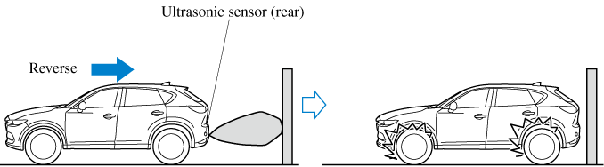
The SCBS R is a system which is designed to reduce damage in the event of a collision by operating the brake control (SCBS brake) when the system’s ultrasonic sensors detect an obstruction at the rear of the vehicle while driving at a speed of about 2 to 8 km/h (2 to 4 mph) and the system determines that a collision is unavoidable.
Do not rely completely on the SCBS R system:
-
The SCBS R system is only designed to reduce damage in the event of a collision. Over reliance on the system leading to the accelerator pedal or brake pedal being mistakenly operated could result in an accident.
-
To assure the correct operation of the SCBS R, heed the following cautions.
-
Do not apply a sticker to an ultrasonic sensor (rear) (including transparent stickers). Otherwise, the ultrasonic sensor (rear) may not be able to detect vehicles or obstructions which could result in an accident.
-
Do not disassemble an ultrasonic sensor (rear).
-
If cracks or damage caused by flying gravel or debris is visible around an ultrasonic sensor (rear), stop using the SCBS R system immediately and have your vehicle inspected by an Authorized Mazda Dealer. If the vehicle continues to be driven with cracks or scratch marks left around an ultrasonic sensor, the system may operate unnecessarily and cause an unexpected accident.
Refer to Stopping the Smart City Brake Support [Reverse] (SCBS R) System Operation (Search).
-
Consult an Authorized Mazda Dealer for rear bumper replacement.
-
Do not modify the suspension:
If the vehicle height or inclination is changed, the SCBS R system may not operate correctly because it cannot detect obstructions correctly.
Do not apply a strong force to an ultrasonic sensor (rear):
When washing the vehicle, do not spray highly pressurized water against an ultrasonic sensor (rear), or rub it strongly. In addition, do not hit the rear bumper forcefully when loading and unloading cargo Otherwise, the sensors may not detect obstructions correctly which could cause the SCBS R system to not operate normally, or it could operate unnecessarily.
-
When driving off-road in areas where there is grass or foliage, it is recommended that the SCBS R system be turned off.
-
Always use tires of the specified size and the same manufacturer, brand, and tread pattern on all 4 wheels. In addition, do not use tires with significantly different wear patterns on the same vehicle. Otherwise, the SCBS R system may not operate normally.
-
If ice or snow is stuck on the ultrasonic sensors (rear) they may not be able to detect obstructions correctly depending on the conditions. In such cases, the system may not be able to perform controls correctly. Always drive carefully and pay attention to the rear of the vehicle.
-
The vehicle posture changes depending on the accelerator pedal, brake pedal and steering wheel operations, which could make it difficult for the system to recognize an obstruction, or it could facilitate unnecessary detection. In such cases, the SCBS R may or may not operate.
-
The SCBS R system will operate under the following conditions.
-
The engine is running.
-
The selector lever is in the R (reverse) position.
-
“Reverse Smart City Brake Support Malfunction” is not displayed in the multi-information display.
-
The vehicle speed is between about 2 to 8 km/h (2 to 4 mph).
-
The SCBS R is not turned off.
-
The DSC is not malfunctioning.
-
-
The SCBS R operates using ultrasonic sensors (rear) which detect obstructions at the rear by emitting ultrasonic waves and then receiving the returning waves reflected off the obstructions.
-
In the following cases, the ultrasonic sensors (rear) cannot detect obstructions and the SCBS R may not operate.
-
The height of the obstruction is low such as low walls or trucks with low loading platforms.
-
The height of the obstruction is high such as trucks with high loading platforms.
-
The obstruction is small.
-
The obstruction is thin such as a signpost.
-
The obstruction is positioned away from the center of the vehicle.
-
The surface of the obstruction is not pointed vertically relative to the vehicle.
-
The obstruction is soft such as a hanging curtain or snow stuck to a vehicle.
-
The obstruction is shaped irregularly.
-
The obstruction is extremely close.
-
-
In the following cases, the ultrasonic sensors (rear) cannot detect obstructions correctly and the SCBS R may not operate.
-
Something is stuck on the bumper near an ultrasonic sensor (rear).
-
The steering wheel is turned sharply, or the brake or accelerator pedal is operated.
-
There is another obstruction near one obstruction.
-
During inclement weather such as rain, fog and snow.
-
High or low humidity.
-
High or low temperatures
-
Strong winds.
-
The path of travel is not flat.
-
Heavy luggage is loaded in the luggage compartment or on the rear seat.
-
Objects such as a wireless antenna, fog light, or illuminated license plate is installed near an ultrasonic sensor (rear).
-
The orientation of an ultrasonic sensor (rear) has deviated for reasons such as a collision.
-
The vehicle is affected by other sound waves such as the horn, engine noise, ultrasonic sensor of another vehicle.
-
-
In the following cases, an ultrasonic sensor (rear) may detect something as a target obstruction which could cause the SCBS R system to operate.
-
Driving on a steep slope.
-
Wheel blocks.
-
Hanging curtains, gate poles such as at toll gates and railroad crossing.
-
When traveling near objects such as foliage, barriers, vehicles, walls, and fences along a road.
-
When driving off-road in areas where there is grass and forage.
-
When passing through low gates, narrow gates, car washing machines, and tunnels.
-
A towing bar is installed or a trailer is connected.
-
-
During the SCBS R brake control, the brake pedal may move rearward or become stiff. The brakes are operating, but continue to depress the brake pedal.
-
When the system operates, the user is notified by the multi-information display.
-
The Smart City Brake Support (SCBS) warning indication (amber) turns on when the system has a malfunction.
Refer to Taking Action (Search).
Automatic Brake Operation Display
“SCBS Automatic Brake” is indicated in the multi-information display after the Smart City Brake Support (SCBS) brakes is operated.

-
The collision warning beep sounds intermittently while the Smart City Brake Support (SCBS) brake is operating.
-
If the vehicle is stopped by the Smart City Brake Support (SCBS) operation and the brake pedal is not depressed, the warning beep sounds one time after about 2 seconds and the Smart City Brake Support (SCBS) brake is automatically released.
Smart Brake Support (SBS) (Some Models)
The SBS system alerts the driver of a possible collision using a display and warning sound if the radar sensor (front) and the Forward Sensing Camera (FSC) determine that there is the possibility of a collision with a vehicle ahead while the vehicle is being driven at about 15 km/h or faster (10 mph or faster). Furthermore, if the radar sensor (front) and the Forward Sensing Camera (FSC) determines that a collision is unavoidable, the automatic brake control is performed to reduce damage in the event of a collision.
In addition, when the driver depresses the brake pedal, the brakes are applied firmly and quickly to assist. (Brake Assist (SBS brake assist))
Do not rely completely on the SBS system and always drive carefully:
The SBS is designed to reduce damage in the event of a collision, not avoid an accident. The ability to detect an obstruction is limited depending on the obstruction, weather conditions, or traffic conditions. Therefore, if the accelerator pedal or brake pedal is mistakenly operated it could result in an accident. Always verify the safety of the surrounding area and depress the brake pedal or accelerator pedal while keeping a safer distance from vehicles ahead or on-coming vehicles.
In the following cases, turn the system off to prevent a mis-operation:
-
The vehicle is being towed or when towing another vehicle.
-
The vehicle is on a chassis roller.
-
When driving on rough roads such as in areas of dense grass or off-road.
-
The SBS system operates when all of the following conditions are met:
-
The ignition is switched ON.
-
The SBS system is on.
-
The vehicle speed is about 15 km/h or faster (10 mph or faster).
-
The relative speed between your vehicle and the vehicle ahead is about 15 km/h or faster (10 mph or faster).
-
The Dynamic Stability Control (DSC) is not operating.
-
-
The SBS system may not operate under the following conditions:
-
If the vehicle is accelerated rapidly and it comes close to a vehicle ahead.
-
The vehicle is driven at the same speed as the vehicle ahead.
-
The accelerator pedal is depressed.
-
The brake pedal is depressed.
-
The steering wheel is being operated.
-
The selector lever is being operated.
-
The turn signal is being used.
-
When the vehicle ahead is not equipped with taillights or the taillights are turned off.
-
When warnings and messages, such as a dirty windshield, related to the Forward Sensing Camera (FSC) are being displayed in the multi-information display.
-
-
Although the objects which activate the system are four-wheeled vehicles, the radar sensor (front) could detect the following objects, determine them to be an obstruction, and operate the SBS system.
-
Objects on the road at the entrance to a curve (including guardrails and snow banks).
-
A vehicle appears in the opposite lane while cornering or rounding a curve.
-
When crossing a narrow bridge.
-
When passing under a low gate or through a tunnel or narrow gate.
-
When entering an underground parking area.
-
Metal objects, bumps, or protruding objects on the road.
-
If you suddenly come close to a vehicle ahead.
-
When driving in areas where there is high grass or forage.
-
Two-wheeled vehicles such as motorbikes or bicycles.
-
Pedestrians or non-metallic objects such as standing trees.
-
-
During the SBS brake control, the brake pedal may move rearward or become stiff. The brakes are operating, but continue to depress the brake pedal.
-
When the system operates, the user is notified by the multi-information display.
-
The SBS warning indication (amber) turns on when the system has a malfunction.
Refer to Taking Action (Search).
Collision Warning
If there is the possibility of a collision with a vehicle ahead, the beep sounds continuously and a warning is indicated in the multi-information display and the active driving display.
How to Use the System
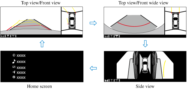
Top view/Front view, Top view/Front wide view, Side view
Indication
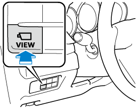
Images are displayed on the screen when the 360°View Monitor switch is pressed with all of the following conditions met.
-
The ignition is switched ON.
-
The selector lever is in a position other than R.
Display switching
The displayed screen can be changed each time the 360°view monitor switch is pressed.
-
When the selector lever is in R position, the displayed screen does not switch to the top view/front view, top view/front wide view, or the side view.
-
Display of the top view/front view, top view/front wide view, or the side view stops even with the display conditions met if any of the following conditions occurs.
-
When a switch around the commander knob is pressed.
-
The selector lever is shifted to P position (displayed when the selector lever is in a position other than P).
-
(Displayed when vehicle speed is less than 15 km/h (9.3 mph))
-
4 minutes and 30 seconds have passed.
-
The vehicle speed is about 15 km/h (9.3 mph) or faster.
-
-
(Displayed when the vehicle speed is about 15 km/h (9.3 mph) or faster)
-
The vehicle speed is about 15 km/h (9.3 mph) or faster after 8 seconds have passed since pressing the 360°View Monitor switch.
-
4 minutes and 22 seconds have passed from the point when the vehicle speed was less than 15 km/h (9.3 mph) after 8 seconds have passed since pressing the 360°View Monitor switch.
-
-
-
The 360°View Monitor settings can be changed as follows.
Refer to the Settings section in the Mazda Connect Owner's Manual.
-
Automatic display of the 360°View Monitor when the ultrasonic sensor detects an obstruction.
-
Automatic display of the 360°View Monitor when the ignition is switched ON.
-
Screen priority level when the system launches.
-
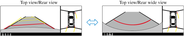
Top view/Rear view, Top view/Rear wide view
The top view/rear view, top view/rear wide view displays when all of the following conditions are met.
-
The ignition is switched ON.
-
Selector lever is in R position.
Display switching
The displayed screen can be changed each time the 360°view monitor switch is pressed.
-
The top view/rear view and top view/rear wide view automatically display whether or not the 360°View Monitor switch is turned on or off when shifting the selector lever to R position.
-
The top view/rear view and top view/rear wide view displays the previously displayed screen.
-
The setting can be changed to display the top view/front view when shifting from reverse to a forward gear without operating the 360°View Monitor switch to check the front of the vehicle while parallel parking.
Refer to the Settings section in the Mazda Connect Owner's Manual.
Screen operation/icon
Always stop the vehicle when adjusting the 360°View Monitor image quality.
Do not adjust the 360°View Monitor image quality while driving. If you adjust the 360°View Monitor image quality (such as brightness, contrast, tone, and color density) while driving, it could lead to an unexpected accident.
|
Display/Icon |
Content |
|
|---|---|---|
|
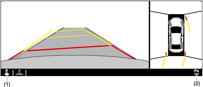
(1) |
View status icon |
Indicates which image is displayed among the front view/front wide view/side view/rear view/rear wide view. |
|
(2) |
Parking sensor status icon |
Indicates that the parking sensor has a problem or it is switched off. |
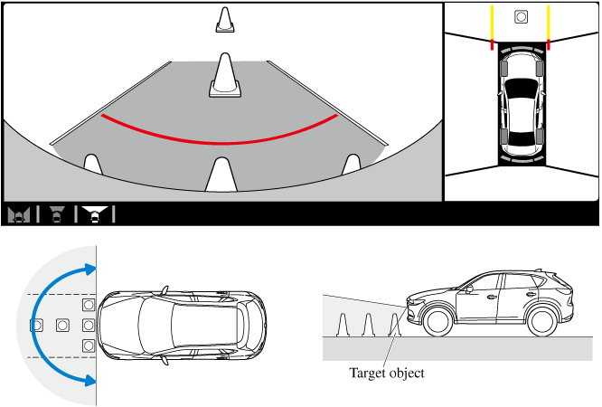
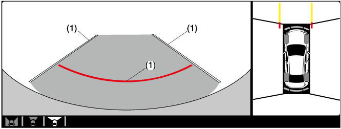
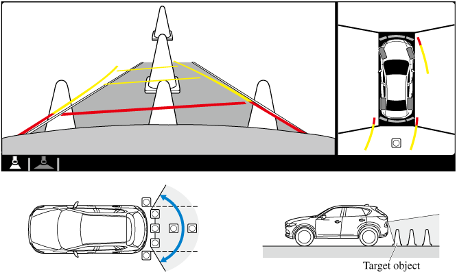
Top View/Front Wide View
Use the top view/front wide view to assist in checking the safety of the surrounding area when accelerating from a stop or entering a T-shaped intersection and intersection.
Display range
-
In the top view screen, the areas in black at the front and rear of the vehicle image and the seams where each of the camera images merge are blind spots.
-
Because images displayed in the top view screen are processed from each camera, the top view screen may display in the following ways.
-
If an image containing an object with a conspicuous color is picked up by any of the cameras, the screen area for each camera may be affected and it may display in that color.
-
Obstructions displayed in the front view may not display on the top view screen.
-
If the position or angle of each camera changes due to tilting of the vehicle, the image may appear distorted.
-
Lines on the road may appear distorted at the seams where each of the camera images merge.
-
The screen area for each camera may appear bright/dark depending on the illumination level around any of the cameras.
-
Viewing the screen
|
Display/Icon |
Content |
|
|---|---|---|
|
(1) |
Extended vehicle width lines and distance guide lines (blue & red) |
Indicates the approximate width of the vehicle and the distance (from front end of bumper) in front of the vehicle.
|
The front wide view screen displays the image in front of the vehicle at a wide angle and corrects the image to help detect approaching obstructions from the side. Therefore, it differs from the actual view.
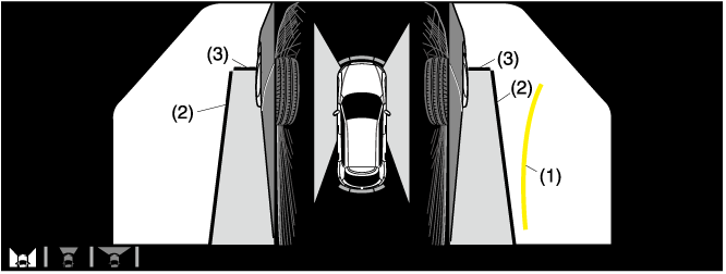
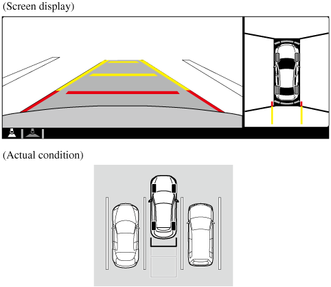
Side View
Use the side view to assist in checking the safety of the surrounding area when accelerating from a stop, parking, or stopping the vehicle.
Display range
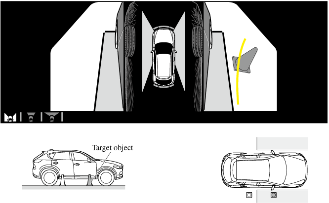
Viewing the screen
|
Display/Icon |
Content |
|
|---|---|---|
|
(1) |
Projected vehicle path lines (yellow) |
Indicates the approximate projected path of the vehicle. Moves in conjunction with the steering wheel operation. The projected vehicle path lines (yellow) indicate the path the inner side of the vehicle is expected to travel. |
|
(2) |
Vehicle parallel guide lines (blue) |
Indicates the approximate vehicle width including the door mirrors. |
|
(3) |
Vehicle front end guide lines (blue) |
Indicates the point about 0.25 m (9.8 in) from the front edge of the vehicle (front edge of the bumper). |
The setting can be changed so that the projected vehicle path lines are not displayed.
Refer to the Settings section in the Mazda Connect Owner's Manual.
How to use the projected vehicle path line function
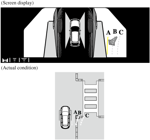
Make sure that there are no obstructions within the projected vehicle path lines.
Turn the steering wheel so that the projected vehicle path lines travel inside of the obstruction (A), and drive the vehicle forward until it passes the obstruction.
If the projected vehicle path lines are on an obstruction (B) or outside of the obstruction (C), the vehicle may contact the obstruction when turning the vehicle sharply.
-
The parking sensor detection range has limitations. For example, obstructions closing in from the side and objects short in height may not be detected. Always confirm the safety around the vehicle visually when driving.
For details, refer to the parking sensor obstruction detection indication and warning sound.
Refer to Parking Sensor System (Search).
-
Do not turn the steering wheel any more until the vehicle has passed the obstruction, even if the obstruction is not visible on the side view image. If the steering wheel is turned even more, the vehicle may contact the obstruction if it is turned sharply.
-
Because there might be a difference between the image displayed on the screen and the actual conditions, always check the safety of the surrounding area using the mirrors and directly with your eyes when driving.
-
Even though the object displayed on the screen, such as a road curb or a division line of a parking space, and the vehicle parallel guide lines appear parallel, they may not actually be parallel.
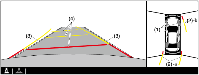
Top View/Rear View
Use the top view/rear view to assist in checking the safety of the surrounding area when accelerating from a stop, parking, or stopping the vehicle.
Range of displayed screen image
-
In the top view screen, the areas in black at the front and rear of the vehicle image and the seams where each of the camera images merge are blind spots.
-
Because images displayed in the top view screen are processed from each camera, the top view screen may display in the following ways.
-
If an image containing an object with a conspicuous color is picked up by any of the cameras, the screen area for each camera may be affected and it may display in that color.
-
Obstructions displayed in the rear view may not display on the top view screen.
-
If the position or angle of each camera changes due to tilting of the vehicle, the image may appear distorted.
-
Lines on the road may appear distorted at the seams where each of the camera images merge.
-
The screen area for each camera may appear bright/dark depending on the illumination level around any of the cameras.
-
Viewing the screen
|
Display/Icon |
Content |
|
|---|---|---|
|
(1) |
Tire icon |
Indicates the tire direction. Moves in conjunction with the steering wheel operation. |
|
(2) |
Projected vehicle path lines (yellow & red) |
Indicates the approximate projected path of the vehicle. Moves in conjunction with the steering wheel operation. a) Indicates the path where the edge of the rear bumper is expected to travel. b) Indicates the path where the outer side of the vehicle is expected to travel. |
|
(3) |
Extended vehicle width lines (blue) |
These guide lines indicate the approximate width of the vehicle. |
|
(4) |
Projected vehicle path distance guide lines (yellow & red) |
These guide lines indicate the approximate distance to a point measured from the rear of the vehicle (from the end of the bumper).
|
The setting can be changed so that the projected vehicle path lines are not displayed.
Refer to the Settings section in the Mazda Connect Owner's Manual.
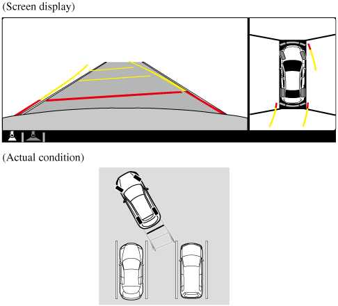
How to use the projected vehicle path line function
-
The front of the vehicle swings out wide when turning the steering wheel while reversing. Maintain sufficient distance between the vehicle and an obstruction.
-
The parking sensor detection range has limitations. For example, obstructions closing in from the side and objects short in height may not be detected. Always confirm the safety around the vehicle visually when driving.
For details, refer to the parking sensor obstruction detection indication and warning sound.
Refer to Parking Sensor System (Search).
-
Because there might be a difference between the image displayed on the screen, such as indicated in the following, and the actual conditions when parking, always check the safety at the rear of the vehicle and the surrounding area directly with your eyes.
-
Even though the back end of the parking space (or garage) displayed on the screen and distance guide lines appear parallel, they may not actually be parallel.
-
When parking in a space with a division line on only one side of the parking space, even though the division line and the vehicle width guide line appear parallel, they may not actually be parallel.
-
-
The following shows an example of vehicle parking with the steering wheel turned to the left while backing up the vehicle. When backing into a parking space from the opposite direction, the steering operation is reversed.
-
Back the vehicle into the parking space by turning the steering wheel so that the vehicle enters the center of the parking space.
-
After the vehicle starts entering the parking space, stop and adjust the steering wheel so that the distance between the vehicle width lines and the sides of the parking space on the left and right are roughly equal, and then continue backing up slowly.
-
Once the vehicle width lines and the sides of the parking space on the left and right are parallel, straighten the wheels and back the vehicle slowly into the parking space. Continue checking the vehicle's surroundings and then stop the vehicle in the best possible position. (If the parking space has division lines, check whether the vehicle width guide lines are parallel to them.)
Forward Sensing Camera (FSC) (Some Models)
Your vehicle is equipped with a Forward Sensing Camera (FSC). The Forward Sensing Camera (FSC) is positioned near the rearview mirror and used by the following systems.
-
High Beam Control System (HBC)
-
Driver Attention Alert (DAA)
-
Lane-keep Assist System (LAS) & Lane Departure Warning System (LDWS)
-
Traffic Sign Recognition System (TSR)
-
Advanced Smart City Brake Support (Advanced SCBS)
-
Smart City Brake Support [Forward] (SCBS F)
-
Mazda Radar Cruise Control with Stop & Go function (MRCC with Stop & Go function)
-
Traffic Jam Assist (TJA)
-
Smart Brake Support (SBS)
The Forward Sensing Camera (FSC) determines the conditions ahead of the vehicle while traveling at night and detects traffic lanes. The distance in which the Forward Sensing Camera (FSC) can detect objects varies depending on the surrounding conditions.
Do not modify the suspension:
If the vehicle height or inclination is changed, the system will not be able to correctly detect vehicles ahead. This will result in the system not operating normally or mistakenly operating, which could cause a serious accident.
-
Do not apply accessories, stickers or film to the windshield near the Forward Sensing Camera (FSC).
If the area in front of the Forward Sensing Camera (FSC) lens is obstructed, it will cause the system to not operate correctly. Consequently, each system may not operate normally which could lead to an unexpected accident.
-
Do not disassemble or modify the Forward Sensing Camera (FSC).
Disassembly or modification of the Forward Sensing Camera (FSC) will cause a malfunction or mistaken operation. Consequently, each system may not operate normally which could lead to an unexpected accident.
-
Heed the following cautions to assure the correct operation of the Forward Sensing Camera (FSC).
-
Be careful not to scratch the Forward Sensing Camera (FSC) lens or allow it to get dirty.
-
Do not remove the Forward Sensing Camera (FSC) cover.
-
Do not place objects on the dashboard which reflect light.
-
Always keep the windshield glass around the camera clean by removing dirt or fogging. Use the windshield defroster to remove fogging on the windshield.
-
Consult an Authorized Mazda Dealer regarding cleaning the interior side of the windshield around the Forward Sensing Camera (FSC).
-
Consult an Authorized Mazda Dealer before performing repairs around the Forward Sensing Camera (FSC).
-
The Forward Sensing Camera (FSC) is installed to the windshield. Consult an Authorized Mazda Dealer for windshield repair and replacement.
-
When cleaning the windshield, do not allow glass cleaners or similar cleaning fluids to get on the Forward Sensing Camera (FSC) lens. In addition, do not touch the Forward Sensing Camera (FSC) lens.
-
When performing repairs around the rearview mirror, consult an Authorized Mazda Dealer.
-
Consult an Authorized Mazda Dealer regarding cleaning of the camera lens.
-
Do not hit or apply strong force to the Forward Sensing Camera (FSC) or the area around it. If the Forward Sensing Camera (FSC) is severely hit or if there are cracks or damage caused by flying gravel or debris in the area around it, stop using the following systems and consult an Authorized Mazda Dealer.
-
High Beam Control System (HBC)
-
Driver Attention Alert (DAA)
-
Lane-keep Assist System (LAS) & Lane Departure Warning System (LDWS)
-
Traffic Sign Recognition System (TSR)
-
Advanced Smart City Brake Support (Advanced SCBS)
-
Smart City Brake Support [Forward] (SCBS F)
-
Mazda Radar Cruise Control with Stop & Go function (MRCC with Stop & Go function)
-
Traffic Jam Assist (TJA)
-
Smart Brake Support (SBS)
-
-
The direction in which the Forward Sensing Camera (FSC) is pointed has been finely adjusted. Do not change the installation position of the Forward Sensing Camera (FSC) or remove it. Otherwise, it could result in damage or malfunction.
-
-
Always use tires for all wheels that are of the specified size, and the same manufacturer, brand, and tread pattern. In addition, do not use tires with significantly different wear patterns on the same vehicle as the system may not operate normally.
-
The Forward Sensing Camera (FSC) includes a function for detecting a soiled windshield and informing the driver, however, depending on the conditions, it may not detect plastic shopping bags, ice or snow on the windshield. In such cases, the system cannot accurately determine a vehicle ahead and may not be able to operate normally. Always drive carefully and pay attention to the road ahead.
-
In the following cases, the Forward Sensing Camera (FSC) cannot detect target objects correctly, and each system may be unable to operate normally.
-
The height of the vehicle ahead is low.
-
You drive your vehicle at the same speed as the vehicle ahead.
-
Headlights are not turned on during the night or when going through a tunnel.
-
-
In the following cases, the Forward Sensing Camera (FSC) may not be able to detect target objects correctly.
-
Under bad weather condition, such as rain, fog and snow.
-
The window washer is being used or the windshield wipers are not used when it's raining.
-
Ice, fog, snow, frost, rainfall, dirt, or foreign matter such as a plastic bag is stuck on the windshield.
-
Trucks with low loading platforms and vehicles with an extremely low or high profile.
-
When driving next to walls with no patterning (including fences and longitudinally striped walls).
-
The taillights of the vehicle ahead are turned off.
-
A vehicle is outside the illumination range of the headlights.
-
The vehicle is making a sharp turn, or ascending or descending a steep slope.
-
Entering or exiting a tunnel.
-
Heavy luggage is loaded causing the vehicle to tilt.
-
Strong light is shone at the front of the vehicle (back light or high-beam light from on-coming vehicles).
-
There are many light emitters on the vehicle ahead.
-
When the vehicle ahead is not equipped with taillights or the taillights are turned off at nighttime.
-
Elongated luggage or cargo is loaded onto installed roof rails and covers the Forward Sensing Camera (FSC).
-
Exhaust gas from the vehicle in front, sand, snow, and water vapor rising from manholes and grating, and water splashed into the air.
-
When towing a malfunctioning vehicle.
-
The vehicle is driven with tires having significantly different wear.
-
The vehicle is driven on down slopes or bumpy roads.
-
There are water puddles on the road.
-
The surroundings are dark such as during the night, early evening, or early morning, or in a tunnel or indoor parking lot.
-
The illumination brightness of the headlights is reduced or the headlight illumination is weakened due to dirt or a deviated optical axis.
-
The target object enters the blind spot of the Forward Sensing Camera (FSC).
-
A person or object bursts onto the road from the shoulder or cuts right in front of you.
-
You change lanes and approach a vehicle ahead.
-
When driving extremely close to the target object.
-
Tire chains or a temporary spare tire is installed.
-
The vehicle ahead has a special shape. For example, a vehicle towing a trailer house or a boat, or a vehicle carrier carrying a vehicle with its front pointed rearward.
-
-
If the Forward Sensing Camera (FSC) cannot operate normally due to backlight or fog, the system functions related to the Forward Sensing Camera (FSC) are temporarily stopped and the following warning lights turn on. However, this does not indicate a malfunction.
-
High Beam Control System (HBC) warning light (amber)
-
Lane-keep Assist System (LAS) & Lane Departure Warning System (LDWS) warning indication
-
Mazda Radar Cruise Control with Stop & Go function (MRCC with Stop & Go function) warning indication
-
Traffic Jam Assist (TJA) warning indication
-
Smart Brake Support/Smart City Brake Support (SBS/SCBS) warning indication/warning light (amber)
-
-
If the Forward Sensing Camera (FSC) cannot operate normally due to high temperatures, the system functions related to the Forward Sensing Camera (FSC) are temporarily stopped and the following warning lights turn on. However, this does not indicate a malfunction. Cool down the area around the Forward Sensing Camera (FSC) such as by turning on the air conditioner.
-
High Beam Control System (HBC) warning light (amber)
-
Lane-keep Assist System (LAS) & Lane Departure Warning System (LDWS) warning indication
-
Mazda Radar Cruise Control with Stop & Go function (MRCC with Stop & Go function) warning indication
-
Traffic Jam Assist (TJA) warning indication
-
Smart Brake Support/Smart City Brake Support (SBS/SCBS) warning indication/warning light (amber)
-
-
If the Forward Sensing Camera (FSC) detects that the windshield is dirty or foggy, the system functions related to the Forward Sensing Camera (FSC) are temporarily stopped and the following warning lights turn on. However, this does not indicate a problem. Remove the dirt from the windshield or press the defroster switch and defog the windshield.
-
High Beam Control System (HBC) warning light (amber)
-
Lane-keep Assist System (LAS) & Lane Departure Warning System (LDWS) warning indication
-
Mazda Radar Cruise Control with Stop & Go function (MRCC with Stop & Go function) warning indication
-
Traffic Jam Assist (TJA) warning indication
-
Smart Brake Support/Smart City Brake Support (SBS/SCBS) warning indication/warning light (amber)
-
-
If there are recognizable cracks or damage caused by flying gravel or debris on the windshield, always have the windshield replaced. Consult an Authorized Mazda Dealer for replacement.
-
(With Advanced Smart City Brake Support (Advanced SCBS))
-
The Forward Sensing Camera (FSC) recognizes pedestrians when all of the following conditions are met:
-
The height of a pedestrian is about 1 to 2 meters.
-
An outline such as the head, both shoulders, or the legs can be determined.
-
-
In the following cases, the Forward Sensing Camera (FSC) may not be able to detect target objects correctly:
-
Multiple pedestrians are walking, or there are groups of people.
-
A pedestrian is close to a separate object.
-
A pedestrian is crouching, lying, or slouching.
-
A pedestrian suddenly jumps into the road right in front of the vehicle.
-
A pedestrian opens an umbrella, or is carrying large baggage or articles.
-
A pedestrian is in a dark location such as during the night, or blends into the background by wearing clothes matching the background color.
-
-
Radar Sensors (Rear) (Some Models)
Your vehicle is equipped with radar sensors (rear). The following systems also use the radar sensors (rear).
-
Blind Spot Monitoring system (BSM)
-
Rear Cross Traffic Alert (RCTA)
The radar sensors (rear) function by detecting the radio waves reflected off a vehicle approaching from the rear or an obstruction sent from the radar sensor.
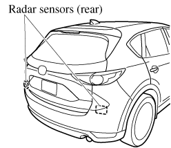
The radar sensors (rear) are installed inside the rear bumper, one each on the left and right sides.
Always keep the surface of the rear bumper near the radar sensors (rear) clean so that the radar sensors (rear) operate normally. Also, do not apply items such as stickers.
Refer to Exterior Care (Search).
If the rear bumper receives a severe impact, the system may no longer operate normally. Stop the system immediately and have the vehicle inspected at an Authorized Mazda Dealer.
-
The detection ability of the radar sensors (rear) has limitations. In the following cases, the detection ability may lower and the system may not operate normally.
-
The rear bumper near the radar sensors (rear) has become deformed.
-
Snow, ice or mud adheres to the radar sensors (rear) on the rear bumper.
-
Under bad weather conditions such as rain, snow and fog.
-
-
Under the following conditions, the radar sensors (rear) cannot detect target objects or it may be difficult to detect them.
-
Stationary objects on a road or a road side such as small, two-wheeled vehicles, bicycles, pedestrians, animals, and shopping carts.
-
Vehicle shapes which do not reflect radar waves well such as empty trailers with a low vehicle height and sports cars.
-
-
Vehicles are shipped with the direction of the radar sensors (rear) adjusted for each vehicle to a loaded vehicle condition so that the radar sensors (rear) detect approaching vehicles correctly. If the direction of the radar sensors (rear) has deviated for some reason, have the vehicle inspected at an Authorized Mazda Dealer.
-
For repairs or replacement of the radar sensors (rear), or bumper repairs, paintwork, and replacement near the radar sensors, consult an Authorized Mazda Dealer.
-
Turn off the system while pulling a trailer or while an accessory such as a bicycle carrier is installed to the rear of the vehicle. Otherwise, the radio waves emitted by the radar will be blocked causing the system to not operate normally.
-
The radar sensors are regulated by the relevant radio wave laws of the country in which the vehicle is driven. If the vehicle is driven abroad, authorization from the country in which the vehicle is driven may be required.
Ultrasonic Sensor (Rear) (Some Models)
The ultrasonic sensors (rear) function by emitting ultrasonic waves which are reflected off obstructions at the rear and the returning ultrasonic waves are picked up by the ultrasonic sensors (rear).
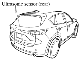
The ultrasonic sensors (rear) are mounted in the rear bumper.
