i-ACTIVSENSE


High Beam Control System (HBC) (Some Models)
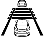
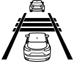
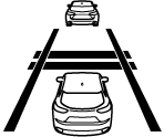
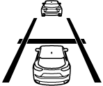
The HBC determines the conditions in front of the vehicle using the Forward Sensing Camera (FSC) while driving in darkness to automatically switch the headlights between high and low beams.
Refer to Forward Sensing Camera (FSC) (Search).
While driving the vehicle at a speed of about 30 km/h (19 mph) or more, the headlights are switched to high beams when there are no vehicles ahead or approaching in the opposite direction.
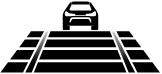
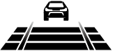
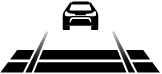
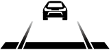
The system switches the headlights to low beams when one of the following occurs:
-
The system detects a vehicle or the headlights/lights of a vehicle approaching in the opposite direction.
-
The vehicle is driven on roads lined with streetlamps or on roads in well-lit cities and towns.
-
The vehicle is driven at less than about 20 km/h (12 mph).

The warning light turns on when the system has a malfunction.
Refer to Contact Authorized Mazda Dealer and Have Vehicle Inspected (Search).
-
Do not adjust the vehicle height, modify the headlight units, or remove the camera, otherwise the system will not operate normally.
-
Do not rely excessively on the HBC and drive the vehicle while paying sufficient attention to safety. Switch the headlights between the high beams and low beams manually if necessary.


The timing in which the system switches the headlights changes under the following conditions. If the system does not switch the headlights appropriately, manually switch between high and low beams according to the visibility as well as road and traffic conditions.
-
When there are sources of light in the area such as street lamps, illuminated signboards, and traffic signals.
-
When there are reflective objects in the surrounding area such as reflective plates and signs.
-
When visibility is reduced under rain, snow and foggy conditions.
-
When driving on roads with sharp turn or hilly terrain.
-
When the headlights/rear lamps of vehicles in front of you or in the opposite lane are dim or not illuminated.
-
When there is sufficient darkness such as at dawn or dusk.
-
When the luggage compartment is loaded with heavy objects or the rear passenger seats are occupied.
-
When visibility is reduced due to a vehicle in front of you spraying water from its tires onto your windshield.
To Operate the System
The HBC operates to switch the headlights automatically between high and low beams after the ignition is switched ON and the headlight switch is in the AUTO and high beam position.
The HBC determines that it is dark based on the brightness of the surrounding area. At the same time, the HBC indicator light (green) in the instrument cluster illuminates.

-
When the vehicle speed is about 30 km/h (19 mph) or more, the headlights automatically switch to high beams when there are no vehicles ahead or approaching in the opposite direction.
When the vehicle speed is less than about 20 km/h (12 mph), the HBC switches the headlights to low beams.
-
The low beams may not switch to high beams when cornering.
-
Operation of the HBC function can be disabled. Refer to the Settings section in the Mazda Connect Owner's Manual.
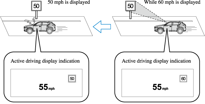
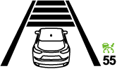
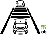
Excessive Speed Warning
If the vehicle speed exceeds the speed limit sign displayed in the active driving display, the area around the speed limit sign flashes 3 times in amber and the warning sound is activated 3 times at the same time. If the vehicle speed continues to exceed the displayed speed limit sign, the indication stops flashing and remains on. Check the surrounding conditions and adjust the vehicle speed to the legal speed using the appropriate operation such as depressing the brake pedal.
The excessive speed warning is initially set to inoperable. If you want to activate the excessive speed warning, change the setting in the personalization features. In addition, the warning pattern and the warning activation timing differ depending on the setting contents.
Refer to the Settings section in the Mazda Connect Owner's Manual.
Warning pattern
-
Off: The excessive speed warning is not activated.
-
Visual: The area around the speed limit sign displayed in the display flashes 3 times in amber, and if the vehicle speed continues to exceed the displayed speed limit sign, the indication stops flashing and remains on.
-
Audio & Visual: The area around the speed limit sign displayed in the display flashes 3 times in amber and the warning sound is activated 3 times at the same time. If the vehicle speed continues to exceed the displayed speed limit sign, the indication stops flashing and remains on.
Warning activation timing
-
 0: If the vehicle speed exceeds the speed limit sign displayed in the display, the excessive speed warning is activated.
 -
5: If the vehicle speed exceeds the speed limit sign displayed in the display by 5 km/h (3 mph), the excessive speed warning is activated.
-
10: If the vehicle speed exceeds the speed limit sign displayed in the display by 10 km/h (5 mph), the excessive speed warning is activated.
-
In the following cases, the excessive speed warning stops operating.
-
The vehicle speed is less than the speed of the displayed speed limit sign. (If the activation timing for the excessive speed warning is changed in the personalization features, the excessive speed warning stops operating when the vehicle speed is less than the changed vehicle speed.
-
A speed limit sign indication has been updated and the vehicle speed is lower than the updated indication.
-
Display of the speed limit sign stops.
-
-
The warning indication is displayed at the same time the excessive speed warning sound is activated if the vehicle speed exceeds the speed indicated on the speed limit sign.
Refer to Warning Sound is Activated (Search).
-
If the Forward Sensing Camera (FSC) incorrectly recognizes the actual speed limit sign at a lower speed, the excessive speed alarm is activated even if the vehicle is driven at the legal speed.
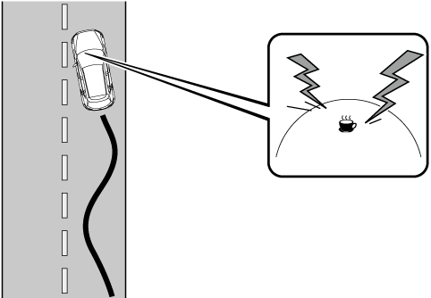
Driver Attention Alert (DAA) (Some Models)
The DAA is a system which detects driver fatigue and decreased attentiveness, and encourages the driver to take a rest.
When the vehicle is driven inside traffic lane lines at about 65 to 140 km/h (40 to 86 mph), the DAA estimates the amount of accumulated fatigue and decreased attentiveness of the driver based on the information from the Forward Sensing Camera (FSC) and other vehicle information, and encourages the driver to take a rest using an indication on the multi-information display and a warning sound.
Use the DAA on expressways or highways.
Refer to Forward Sensing Camera (FSC) (Search).
Do not rely completely on DAA and always drive carefully:
The DAA detects driver fatigue and decreased attentiveness and encourages the driver to take a rest, however, it is not designed to prevent the vehicle from straying. If you rely too much on the DAA it could lead to an accident. Drive carefully and operate the steering wheel appropriately.
In addition, the system may not be able to detect driver fatigue and decreased attentiveness correctly depending on the traffic and driving conditions. The driver must take sufficient rest in consideration of safer driving.
-
The DAA operates when all of the following conditions are met.
-
The vehicle speed is about 65 to 140 km/h (40 to 86 mph).
-
The system detects white (yellow) lane lines.
-
The system has completed learning of the driver’s driving data.
-
-
The DAA does not operate under the following conditions.
-
The vehicle speed is less than about 65 km/h (40 mph).
-
The vehicle speed exceeds about 140 km/h (86 mph)
-
The vehicle is making a sharp turn.
-
The vehicle is changing lanes.
-
The system cannot detect white (yellow) lane lines.
-
-
The DAA may not operate normally under the following conditions.
-
White (yellow) lane lines are less visible because of dirt or fading/patchiness.
-
The vehicle is jolted or swayed continuously by strong winds or rough roads.
-
The vehicle is driven aggressively.
-
When making frequent lane changes.
-
-
The DAA detects driver fatigue and decreased attentiveness based on the driving data when the vehicle is driven at about 65 to 140 km/h (40 to 86 mph) for about 20 minutes. The driving data will be reset under the following conditions.
-
The vehicle is stopped for 15 minutes or longer.
-
The vehicle is driven at less than about 65 km/h (40 mph) for about 30 minutes.
-
The ignition is switched off.
-
-
After the DAA has displayed the first message encouraging rest, it does not display the next one until 45 minutes have passed.
Setting the System
The MRCC with Stop & Go function system operates when all of the following conditions are met.
-
Vehicle speed is 0 km/h (0 mph) to 145 km/h (90 mph)
-
The MRCC with Stop & Go function is turned on.
-
The brake pedal is not depressed.
-
The parking brake is released (Electric Parking Brake (EPB) indicator light is turned off).
-
There is no problem with the DSC.
-
All the doors are closed.
-
The driver's seat belt is fastened.
-
The selector lever is in the drive (D) position or manual (M) position (manual mode).
-
In the following cases, the MRCC with Stop & Go function system is canceled when the vehicle is traveling at 30 km/h (20 mph) or less and “Mazda Radar Cruise Control disabled under 30 km/h (20 mph)” is displayed in the multi-information display.
-
The Forward Sensing Camera (FSC) cannot detect target objects (There is problem with the Forward Sensing Camera (FSC) or windshield is dirty).
-
There is a problem with the stop hold control function.
-
There is a problem with the Electric Parking Brake (EPB).
-
-
It may not be possible to set the MRCC with Stop & Go function system directly after starting the engine, while the DSC operation is being checked.
-
(With Selective Catalytic Reduction (SCR) system)
It is not possible to set the MRCC with Stop & Go function system while the vehicle speed is limited by the Selective Catalytic Reduction (SCR) system.
Turning on the system
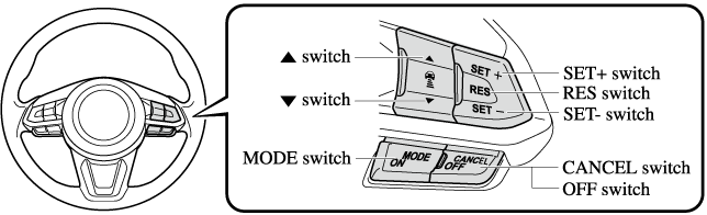
When the MODE switch is pressed once, the MRCC with Stop & Go function system turns on, and the MRCC with Stop & Go function main indication (white) turns on and the vehicle speed and the distance between the vehicles while in headway control can be set.
In addition, the MRCC with Stop & Go function system display indication is displayed on the multi-information display and the active driving display at the same time.
-
If the ignition is switched off while the MRCC with Stop & Go function system is operating, the system will be operable when the ignition is switched ON the next time.
-
The MRCC with Stop & Go function can switch to the cruise control function.
Refer to Cruise Control Function (Search).
How to set the speed
-
Adjust the vehicle speed to the desired setting using the accelerator pedal.
-
Headway control begins when the SET
 or SET
 switch is pressed.
The set speed and the inter-vehicle distance display filled with white lines is displayed. The MRCC with Stop & Go function main indication (white) switches to the MRCC with Stop & Go function set indication (green) at the same time.
|
Travel status |
Indication on multi-information display |
Indication on active driving display |
|
|---|---|---|---|
|
Type A |
Type B |
||
|
During travel at constant speed |
 |
 |
 |
|
During travel under headway control |
 |
 |
 |
-
If a vehicle ahead is detected while traveling at a constant speed, the vehicle-ahead indication is displayed and headway control is performed. Additionally, when a vehicle ahead is no longer detected, the vehicle-ahead indication turns off and the system switches back to travel at constant speed.
-
The lowest possible speed which can be set on the MRCC with Stop & Go function system is 30 km/h (19 mph).
-
Headway control is not possible if the vehicle ahead is driving faster than your vehicle's set speed. Adjust the system to the desired vehicle speed using the accelerator pedal.
How to set the distance-between-vehicles during headway control
The distance-between-vehicles is set to a shorter distance by pressing the  switch. The distance-between-vehicles is set to a longer distance by pressing the
  switch. The distance-between-vehicles can be set to 4 levels; Long, medium, short, and extremely short distance.
|
Distance-between-vehicles guideline (at 80 km/h (50 mph) vehicle speed) |
Indication on multi-information display |
Indication on active driving display*1 |
|
|---|---|---|---|
|
Type A |
Type B |
||
|
Long (about 50 m (164 ft)) |
 |
 |
 |
|
Medium (about 40 m (131 ft)) |
 |
 |
 |
|
Short (about 30 m (98 ft)) |
 |
 |
 |
|
Extremely short (about 25 m (82 ft)) |
 |
 |
 |
-
Displays a pop-up image in the active driving display only when the driver operates the switch.
-
The distance-between-vehicles differs depending on the vehicle speed, and the slower the vehicle speed, the shorter the distance.
-
When the ignition is switched to ACC or OFF and then the engine is started again, the system automatically sets the distance-between-vehicles to the previous setting.
How to change the set vehicle speed
To accelerate/decelerate using the SET switch
When you press the SET switch, the vehicle accelerates and when you press the SET switch, it decelerates.
|
Short press |
1 km/h (1 mph) |
|
Long press |
10 km/h (5 mph) |
For example, the set vehicle speed is changed by pressing the SET switch four times as follows:
The vehicle speed accelerates or decelerates by 4 km/h (4 mph).
To increase speed using accelerator pedal
Depress the accelerator pedal and press and release the SET switch or SET switch at the desired speed. If the switch is not operated, the system returns to the set speed after you release your foot from the accelerator pedal.
The warnings and brake control do not operate while the accelerator pedal is depressed.
-
The setting speed can be changed by operating the SET
switch or SET switch during stop hold control. -
When accelerating using the SET
switch while in headway control, the set vehicle speed can be adjusted but acceleration is not possible. If there is no longer a vehicle ahead, acceleration continues until reaching the set vehicle speed. For the set vehicle speed, check the set vehicle speed indication in the display. -
When depressing the accelerator pedal, the inter-vehicle distance indication in the display changes to the white-line indication.
Canceling the system
When the following operations are performed, the MRCC with Stop & Go function system is canceled, and the MRCC with Stop & Go function set indication (green) switches to the MRCC with Stop & Go function main indication (white) at the same time.
-
The OFF/CANCEL switch is pressed.
-
The brake pedal is depressed.
-
The parking brake is applied.
-
The selector lever is in the P (Park), N (Neutral), or R (Reverse) position.
Under the following conditions, the MRCC with Stop & Go function cancel indication is displayed in the multi-information display and a single beep sound is heard.
-
The DSC has operated.
-
The Smart Brake Support (SBS) has operated.
-
The Smart City Brake Support [Forward] (SCBS F) or Advanced Smart City Brake Support (Advanced SCBS) has operated.
-
When traveling on a downslope for a long period of time.
-
There is a problem with the system.
-
The engine has stalled.
-
Any of the doors is opened.
-
The driver's seat belt is unfastened.
-
The parking brake is automatically applied during stop hold control.
-
The radar sensor (front) cannot detect target objects (during rain, fog, snow or other inclement weather conditions, or when the radiator grille is dirty).
-
(With Selective Catalytic Reduction (SCR) system)
The vehicle speed is limited by the Selective Catalytic Reduction (SCR) system.
Resuming control
If the MRCC with Stop & Go function system is canceled, you can resume control at the previously set speed by pressing the RES switch and after all of the operation conditions have been met.
If the set speed is not indicated in the display, the control does not resume even if the RES switch is pressed.
Turning off the system
Press the OFF/CANCEL switch 2 times while the MRCC with Stop & Go function system is operating to switch off the system.
Stopping the Advanced Smart City Brake Support (Advanced SCBS) System Operation
The Advanced SCBS system can be temporarily deactivated.
Refer to the Settings section in the Mazda Connect Owner's Manual.
When the Advanced SCBS system is turned off, the Smart City Brake Support (SCBS) OFF indicator light turns on.

When the engine is restarted, the system becomes operational.
When the Advanced SCBS system is set to inoperable, the Smart City Brake Support [Reverse] (SCBS R) system and the Smart Brake Support (SBS) are also set to inoperable.
Stopping the Smart City Brake Support (SCBS) System Operation
The SCBS F system can be temporarily deactivated.
Refer to the Settings section in the Mazda Connect Owner's Manual.
When the SCBS F system is turned off, the Smart City Brake Support (SCBS) OFF indicator light turns on.
When the engine is restarted, the system becomes operational.
When the SCBS F system is set to inoperable, the Smart Brake Support (SBS) are also set to inoperable.
Stopping the Smart City Brake Support [Reverse] (SCBS R) System Operation
The SCBS R system can be temporarily deactivated.
Refer to the Settings section in the Mazda Connect Owner's Manual.
When the SCBS R system is turned off, the Smart City Brake Support (SCBS) OFF indicator light turns on.
When the engine is restarted, the system becomes operational.
When the SCBS R system is set to inoperable, Advanced Smart City Brake Support (Advanced SCBS) and the Smart Brake Support (SBS) are also set to inoperable.
How to Use the System
Top view/Front view, Front wide view, Side view
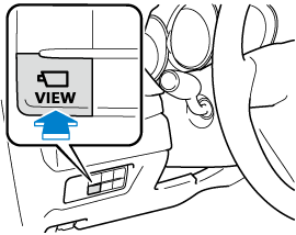
Indication
Images are displayed on the screen when the 360°View Monitor switch is pressed with all of the following conditions met.
-
The ignition is switched ON.
-
The selector lever is in a position other than R.
Display switching
You can change the displayed screen by pressing the commander knob or by touching the switch camera icon on the screen while the top view/front view, front wide view, or the side view is displayed.
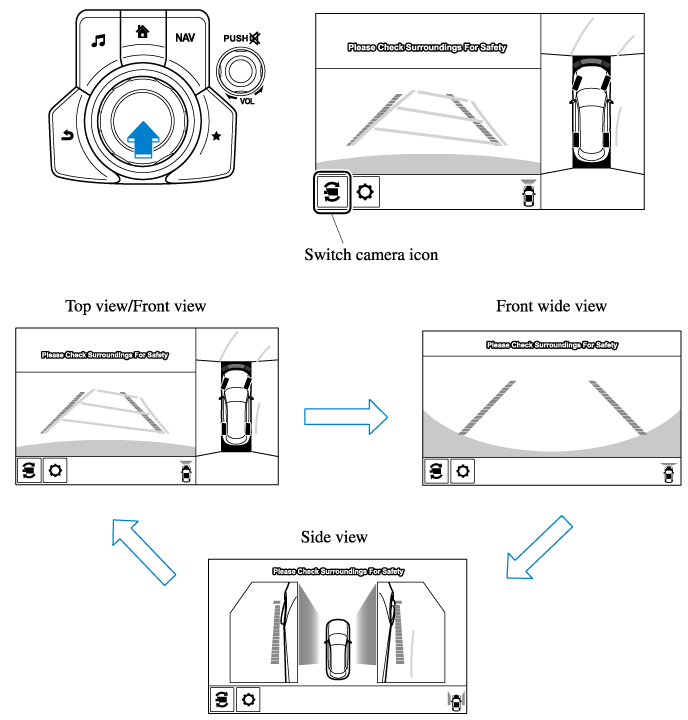
-
When the selector lever is in R position, the displayed screen does not switch to the top view/front view, front wide view, or the side view.
-
Display of the top view/front view, front wide view, or the side view stops even with the display conditions met if any of the following conditions occurs.
-
When a switch around the commander knob is pressed.
-
The selector lever is shifted to P position (displayed when the selector lever is in a position other than P).
-
(Displayed when vehicle speed is less than 15 km/h (9.3 mph))
-
4 minutes and 30 seconds have passed.
-
The vehicle speed is about 15 km/h (9.3 mph) or faster.
-
-
(Displayed when the vehicle speed is about 15 km/h (9.3 mph) or faster)
-
The vehicle speed is about 15 km/h (9.3 mph) or faster after 8 seconds have passed since pressing the 360°View Monitor switch.
-
Four minutes and 22 seconds have passed from the point when the vehicle speed was less than 15 km/h (9.3 mph) after 8 seconds have passed since pressing the 360° View Monitor switch.
-
-
-
The 360°View Monitor displays the previously displayed screen.
-
The 360° View Monitor settings can be changed as follows.
Refer to the Settings section in the Mazda Connect Owner's Manual.
-
Automatic display of the 360°View Monitor when the ultrasonic senor detects an obstruction.
-
Automatic display of the 360°View Monitor when the ignition is switched ON.
-
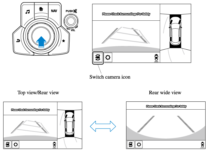
Top view/Rear view, Rear wide view
The top view/rear view, rear wide view displays when all of the following conditions are met.
-
The ignition is switched ON.
-
Selector lever is in R position.
Display switching
The displayed screen can be switched by pressing the commander knob or by touching the switch camera icon on the screen while the top view/rear view, rear wide view is displayed.
-
The top view/rear view and rear wide view automatically display whether or not the 360° View Monitor switch is turned on or off when shifting the selector lever to R position.
-
The setting can be changed to display the top view/front view when shifting from reverse to a forward gear without operating the 360°View Monitor switch to check the front of the vehicle while parallel parking.
Refer to the Settings section in the Mazda Connect Owner's Manual.
Screen operation/icon
Always stop the vehicle when adjusting the 360°View Monitor image quality.
Do not adjust the 360°View Monitor image quality while driving. If you adjust the 360° View Monitor image quality (such as brightness, contrast, tone, and color density) while driving, it could lead to an unexpected accident.
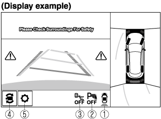
|
Display/Icon |
Content |
|
|---|---|---|
 |
View status icon |
Indicates which image is displayed among the front view/front wide view/side view/rear view/rear wide view. |
 |
Parking sensor status icon |
Indicates that the parking sensor has a problem or it is switched off. |
 |
Rear Cross Traffic Alert (RCTA) status icon |
Indicates that the radar sensor (rear) has a problem or it is turned off. |
 |
Switch camera icon |
Each time the screen is touched, the display screen switches. |
 |
Setting icon |
The image quality for the 360°View Monitor can be adjusted. |
Rear Wide View
360° View Monitor
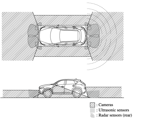
The 360°View Monitor consists of the following functions which assist the driver in checking the area surrounding the vehicle using various indications in the center display and a warning sound while the vehicle is being driven at low speeds or while parking.
-
Top view
The top view displays an image of the vehicle from directly above on the center display by combining the images taken from the 4 cameras set on all sides of the vehicle. The top view displays on the right side of the screen when the front view or rear view screen is being displayed. The top view assists the driver in checking the area surrounding the vehicle when the vehicle is moving forward or in reverse.
-
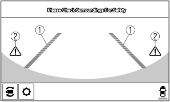
Front view/front wide view
The image from the front of the vehicle is displayed on the center display.
The view from the front assists the driver in checking the front of the vehicle by displaying guide lines on the displayed image taken from the front of the vehicle.
-
Side view
The images taken from the front left and right sides of the vehicle are displayed on the center display.
The side view assists the driver in checking the front sides of the vehicle by displaying guide lines on the displayed image taken from the front left and right sides of the vehicle.
-
Rear view/rear wide view
The image from the rear of the vehicle is displayed on the center display.
The image from the rear assists the driver in checking the rear of the vehicle by displaying guide lines on the displayed image taken from the rear of the vehicle.
-
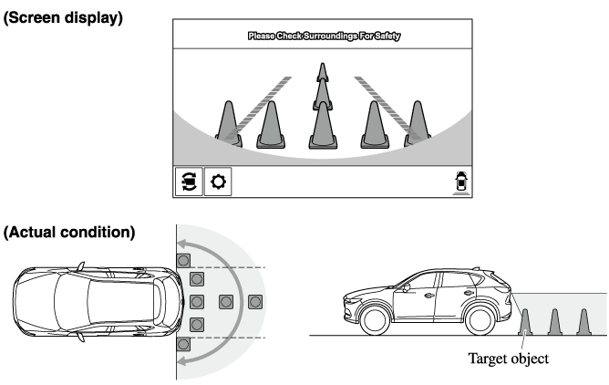
Parking sensor
If there are any obstructions near the vehicle while the top view/side view is displayed, an obstruction detection indication turns on around the bumper in the center display.
The parking sensors use ultrasonic sensors to detect obstructions around the vehicle when the vehicle is driven at low speeds, such as during garage or parallel parking, and notifies the driver of the approximate distance from the vehicle to the surrounding obstruction using sound and an obstruction detection indication.
Refer to Parking Sensor System (Search).
-
Rear Cross Traffic Alert (RCTA)
If there is the possibility of a collision with an approaching vehicle while the rear view/rear wide view is displayed, a warning is displayed on the center display.
The Rear Cross Traffic Alert (RCTA) uses rear side radar sensor to detect vehicles approaching from the rear left and right sides of the vehicle, and it assists the driver in checking the rear of the vehicle while reversing by flashing the Blind Spot Monitoring (BSM) warning lights and activating the warning sound.
Refer to Rear Cross Traffic Alert (RCTA) (Search).
360°View Monitor Range
Always confirm the safety of the area around the vehicle with the mirrors and directly with your eyes when driving:
The 360°View Monitor is an auxiliary device which assists the driver in checking the safety of the area around the vehicle.
The shooting range of the cameras and detection range of the sensors are limited. For example, the areas in black at the front and rear of the vehicle image and the seams where each of the camera images merge are blind spots where an obstruction may not be visible. In addition, the extended vehicle width lines and projected vehicle path lines are only to be used as references, and the images on the screen may differ from the actual conditions.
-
Do not use the 360°View Monitor under any of the following conditions.
-
Icy or snow-covered roads.
-
Tire chains or a temporary spare tire is installed.
-
The front or rear doors are not fully closed.
-
The vehicle is on a road incline.
-
The door mirrors are retracted.
-
-
Do not hit the front/rear camera, front bumper, liftgate, and door mirrors forcefully. The camera position or installation angle may shift.
-
The cameras are waterproof. Do not disassemble, modify, or remove a camera.
-
The camera cover is made of hard plastic, therefore do not apply oil film remover, organic solvents, wax, or coating agents. If any such agent gets on the camera cover, wipe it off using a soft cloth immediately.
-
Do not rub the camera lens forcefully, or clean it with an abrasive or hard brush. Otherwise, it could scratch the camera lens and negatively affect the images.
-
Consult an Authorized Mazda Dealer for repair, painting, or replacement of the front/rear camera, front bumper, liftgate and door mirrors.
-
Heed the following cautions to assure that the 360°View Monitor operates normally.
-
Do not modify the vehicle suspensions or lower/raise the vehicle body, or both.
-
Always use tires of the specified type and size for the front and rear wheels. Consult an Authorized Mazda Dealer for tire replacement.
-
-
When the display is cold, images may leave trails or the screen might be darker than usual, making it difficult to check the vehicle surroundings. Always confirm the safety at the front and around the vehicle visually when driving.
-
The method for parking/stopping the vehicle using the 360°View Monitor differs depending on the road circumstances/conditions and the vehicle conditions. When and how much you turn the steering wheel will differ depending on the situation, , therefore always check the vehicle surroundings directly with your eyes while using the system.
Also, before using the system, always make sure that the vehicle can be parked/stopped in the parking/stopping space.
-
If there are water droplets, snow, or mud on the camera lens, wipe it off using a soft cloth. If the camera lens is especially dirty, wash it off with mild detergent.
-
If the camera lens is touched or there is any dirt on it, it could affect the screen image. Wipe the lens using a soft cloth.
-
If the area where the camera is installed, such as the front bumper, liftgate or door mirrors, has been damaged in a vehicle accident, the camera (position, installation angle) may have shifted. Always consult an Authorized Mazda Dealer to have the vehicle inspected.
-
If the camera is subjected to excessive changes in temperature such as by pouring hot water on the camera during cold weather, the 360°View Monitor may not operate normally.
-
If the battery voltage is low, the screen might be temporarily difficult to view, however, this does not indicate a problem.
-
The 360°View Monitor has limitations. Objects under the bumper or near both ends of the bumper cannot be displayed.
-
Obstructions above the upper image range of the camera are not displayed.
-
Under the following conditions, the screen might be difficult to view, however this does not indicate a problem.
-
The temperature near the lens is high/low.
-
Rainy conditions, water droplets on the camera, or high humidity.
-
Mud or foreign matter near the camera.
-
Extremely bright light such as sunlight or headlights hitting the camera lens directly.
-
The surroundings are illuminated by vehicle lights, fluorescent lights, or LED lights (display may flicker).
-
Extremely small dark or white dots appear on the screen (dots may flicker).
-
-
Because the 360°View Monitor camera uses a special lens, the distance displayed on the screen differs from the actual distance.
-
Obstructions displayed on the screen may appear differently than in actuality. (Obstructions may appear fallen, larger, or longer than they actually are.)
-
Do not apply stickers to a camera or the area around it. In addition, do not install accessories or an illuminated number/character license plate to the area around a camera. Otherwise, the camera may not correctly display the surrounding conditions.
-
Images displayed on the monitor from the 360° view monitor camera are reversed images (mirror images).
-
Free/open source software information
This product includes free/open sources. Information about the licensing and source code is available at the following URL.
Types of Images Displayed on the Screen
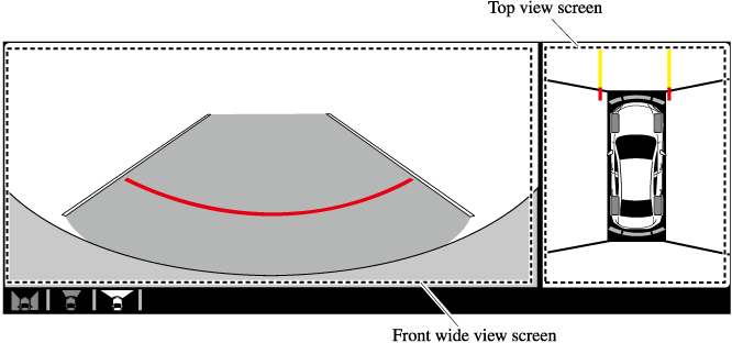
Top view/Front view
Displays the image of the area around the vehicle and the vehicle front.
Top view/Front wide view
Displays the image of the area around the vehicle and the front of the vehicle (wide-area).
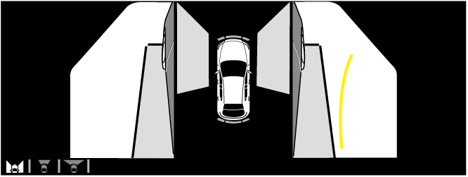
Side view
Displays the image of the left and right sides of the vehicle.
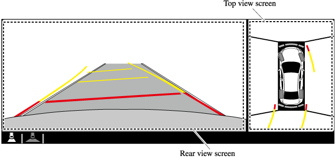
Top view/Rear view
Displays the image of the area around the vehicle and the rear of the vehicle.
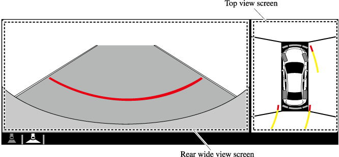
Top view/Rear wide view
Displays the image of the area around the vehicle and the rear of the vehicle (wide-area).
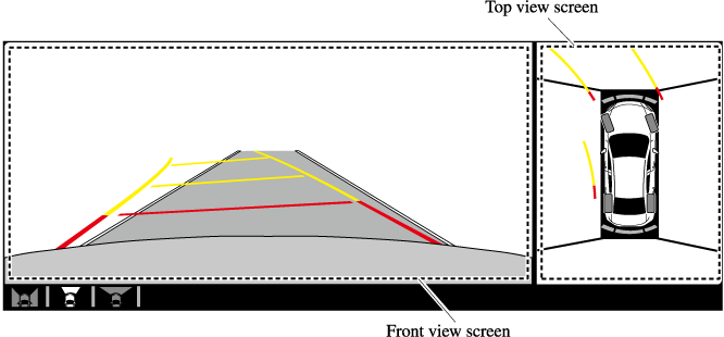
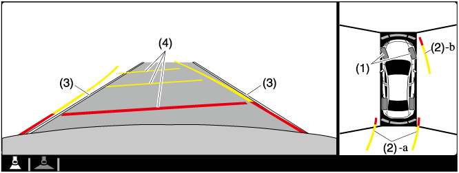
Top View/Front View
Use the top view/front view to assist in checking the safety of the surrounding area when accelerating from a stop, parking, or stopping the vehicle.
Display range
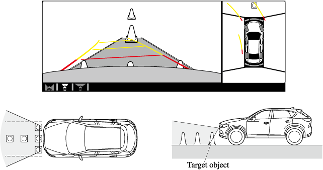
-
In the top view screen, the areas in black at the front and rear of the vehicle image and the seams where each of the camera images merge are blind spots.
-
Because images displayed in the top view screen are processed from each camera, the top view screen may display in the following ways.
-
If an image containing an object with a conspicuous color is picked up by any of the cameras, the screen area for each camera may be affected and it may display in that color.
-
Obstructions displayed in the front view may not display on the top view screen.
-
If the position or angle of each camera changes due to tilting of the vehicle, the image may appear distorted.
-
Lines on the road may appear distorted at the seams where each of the camera images merge.
-
The screen area for each camera may appear bright/dark depending on the illumination level around any of the cameras.
-
Viewing the screen
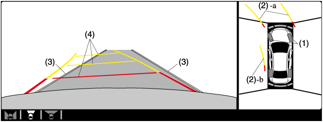
|
Display/Icon |
Content |
|
|---|---|---|
|
(1) |
Tire icon |
Indicates the tire direction. Moves in conjunction with the steering wheel operation. |
|
(2) |
Projected vehicle path lines (yellow & red) |
Indicates the approximate projected path of the vehicle. Moves in conjunction with the steering wheel operation. a) Indicates the path where the edge of the front bumper is expected to travel. b) Indicates the path where the inner side of the vehicle is expected to travel. |
|
(3) |
Extended vehicle width lines (blue) |
Indicates the approximate width of the vehicle. |
|
(4) |
Projected vehicle path distance guide lines (yellow & red) |
Indicates the distance (from front end of bumper) in front of the vehicle.
|
The parking sensor detection range has limitations. For example, obstructions closing in from the side and objects short in height may not be detected. Always confirm the safety around the vehicle visually when driving.
For details, refer to the parking sensor obstruction detection indication and warning sound.
Refer to Parking Sensor System (Search).
The setting can be changed so that the projected vehicle path lines are not displayed.
Refer to the Settings section in the Mazda Connect Owner's Manual.
How to use the projected vehicle path line function
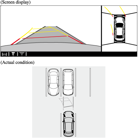
Make sure that there are no obstructions within the projected vehicle path lines.
Drive the vehicle forward while turning the steering wheel so that no obstructions come within the projected vehicle path lines.
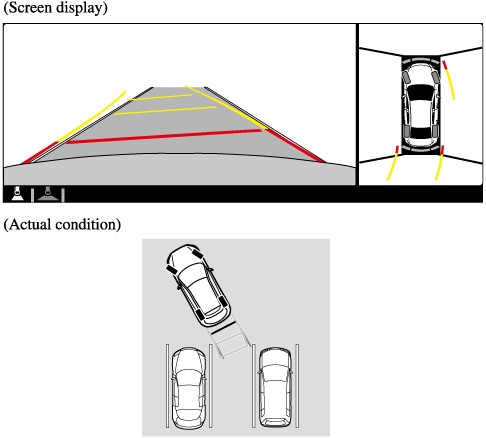
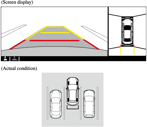
Side View
Use the side view to assist in checking the safety of the surrounding area when accelerating from a stop, parking, or stopping the vehicle.
Display range

Viewing the screen

|
Display/Icon |
Content |
|
|---|---|---|
|
(1) |
Projected vehicle path lines (yellow) |
Indicates the approximate projected path of the vehicle. Moves in conjunction with the steering wheel operation. The projected vehicle path lines (yellow) indicate the path the inner side of the vehicle is expected to travel. |
|
(2) |
Vehicle parallel guide lines (blue) |
Indicates the approximate vehicle width including the door mirrors. |
|
(3) |
Vehicle front end guide lines (blue) |
Indicates the point about 0.25 m (9.8 in) from the front edge of the vehicle (front edge of the bumper). |
The setting can be changed so that the projected vehicle path lines are not displayed.
Refer to the Settings section in the Mazda Connect Owner's Manual.
How to use the projected vehicle path line function
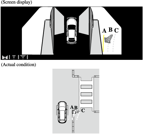
Make sure that there are no obstructions within the projected vehicle path lines.
Turn the steering wheel so that the projected vehicle path lines travel inside of the obstruction (A), and drive the vehicle forward until it passes the obstruction.
If the projected vehicle path lines are on an obstruction (B) or outside of the obstruction (C), the vehicle may contact the obstruction when turning the vehicle sharply.
-
The parking sensor detection range has limitations. For example, obstructions closing in from the side and objects short in height may not be detected. Always confirm the safety around the vehicle visually when driving.
For details, refer to the parking sensor obstruction detection indication and warning sound.
Refer to Parking Sensor System (Search).
-
Do not turn the steering wheel any more until the vehicle has passed the obstruction, even if the obstruction is not visible on the side view image. If the steering wheel is turned even more, the vehicle may contact the obstruction if it is turned sharply.
-
Because there might be a difference between the image displayed on the screen and the actual conditions, always check the safety of the surrounding area using the mirrors and directly with your eyes when driving.
-
Even though the object displayed on the screen, such as a road curb or a division line of a parking space, and the vehicle parallel guide lines appear parallel, they may not actually be parallel.
Top View/Rear View
Use the top view/rear view to assist in checking the safety of the surrounding area when accelerating from a stop, parking, or stopping the vehicle.
Range of displayed screen image

-
In the top view screen, the areas in black at the front and rear of the vehicle image and the seams where each of the camera images merge are blind spots.
-
Because images displayed in the top view screen are processed from each camera, the top view screen may display in the following ways.
-
If an image containing an object with a conspicuous color is picked up by any of the cameras, the screen area for each camera may be affected and it may display in that color.
-
Obstructions displayed in the rear view may not display on the top view screen.
-
If the position or angle of each camera changes due to tilting of the vehicle, the image may appear distorted.
-
Lines on the road may appear distorted at the seams where each of the camera images merge.
-
The screen area for each camera may appear bright/dark depending on the illumination level around any of the cameras.
-
Viewing the screen
|
Display/Icon |
Content |
|
|---|---|---|
|
(1) |
Tire icon |
Indicates the tire direction. Moves in conjunction with the steering wheel operation. |
|
(2) |
Projected vehicle path lines (yellow & red) |
Indicates the approximate projected path of the vehicle. Moves in conjunction with the steering wheel operation. a) Indicates the path where the edge of the rear bumper is expected to travel. b) Indicates the path where the outer side of the vehicle is expected to travel. |
|
(3) |
Extended vehicle width lines (blue) |
These guide lines indicate the approximate width of the vehicle. |
|
(4) |
Projected vehicle path distance guide lines (yellow & red) |
These guide lines indicate the approximate distance to a point measured from the rear of the vehicle (from the end of the bumper).
|
The setting can be changed so that the projected vehicle path lines are not displayed.
Refer to the Settings section in the Mazda Connect Owner's Manual.
How to use the projected vehicle path line function
-
The front of the vehicle swings out wide when turning the steering wheel while reversing. Maintain sufficient distance between the vehicle and an obstruction.
-
The parking sensor detection range has limitations. For example, obstructions closing in from the side and objects short in height may not be detected. Always confirm the safety around the vehicle visually when driving.
For details, refer to the parking sensor obstruction detection indication and warning sound.
Refer to Parking Sensor System (Search).
-
Because there might be a difference between the image displayed on the screen, such as indicated in the following, and the actual conditions when parking, always check the safety at the rear of the vehicle and the surrounding area directly with your eyes.
-
Even though the back end of the parking space (or garage) displayed on the screen and distance guide lines appear parallel, they may not actually be parallel.
-
When parking in a space with a division line on only one side of the parking space, even though the division line and the vehicle width guide line appear parallel, they may not actually be parallel.
-
-
The following shows an example of vehicle parking with the steering wheel turned to the left while backing up the vehicle. When backing into a parking space from the opposite direction, the steering operation is reversed.
-
Back the vehicle into the parking space by turning the steering wheel so that the vehicle enters the center of the parking space.
-
After the vehicle starts entering the parking space, stop and adjust the steering wheel so that the distance between the vehicle width lines and the sides of the parking space on the left and right are roughly equal, and then continue backing up slowly.
-
Once the vehicle width lines and the sides of the parking space on the left and right are parallel, straighten the wheels and back the vehicle slowly into the parking space. Continue checking the vehicle's surroundings and then stop the vehicle in the best possible position. (If the parking space has division lines, check whether the vehicle width guide lines are parallel to them.)
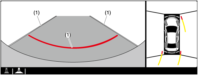
Top View/Rear Wide View
Use the top view/rear wide view to assist in checking the safety of the surrounding area when accelerating from a stop, parking, or stopping the vehicle.
Range of displayed screen image

-
In the top view screen, the areas in black at the front and rear of the vehicle image and the seams where each of the camera images merge are blind spots.
-
Because images displayed in the top view screen are processed from each camera, the top view screen may display in the following ways.
-
If an image containing an object with a conspicuous color is picked up by any of the cameras, the screen area for each camera may be affected and it may display in that color.
-
Obstructions displayed in the front view may not display on the top view screen.
-
If the position or angle of each camera changes due to tilting of the vehicle, the image may appear distorted.
-
Lines on the road may appear distorted at the seams where each of the camera images merge.
-
The screen area for each camera may appear bright/dark depending on the illumination level around any of the cameras.
-
Viewing the screen
|
Display/Icon |
Content |
|
|---|---|---|
|
(1) |
Extended vehicle width lines and distance guide lines (blue & red) |
These guide lines indicate the approximate width of the vehicle and distance to a point measured from the rear of the vehicle (from the end of the bumper).
|
The top view/rear wide view screen displays the image at the rear of the vehicle at a wide angle and corrects the image to help detect approaching obstructions from the side. Therefore, it differs from the actual view.
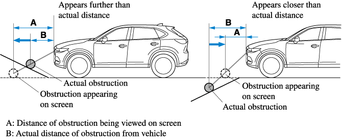
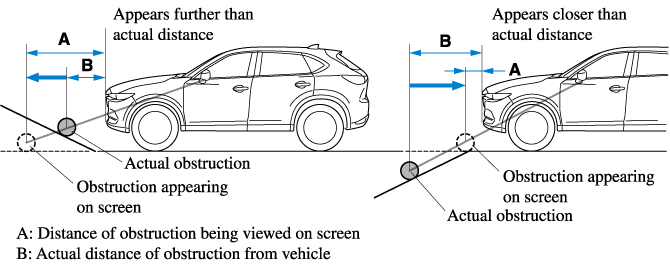
Margin of Error Between Road Surface on Screen and Actual Road Surface
There might be some margin of error between the road surface appearing on the screen and the actual road surface. A margin of error in the perceived distance could lead to an accident, therefore be aware of the following conditions which can more easily produce errors in the perceived distance.
The vehicle tilts due to weight of passengers and cargo.
If the vehicle is tilted, obstructions picked up by a camera can appear farther or closer than the actual distance from the vehicle.
Front camera
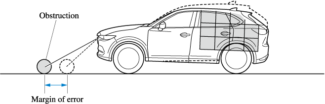
Side camera
Rear camera
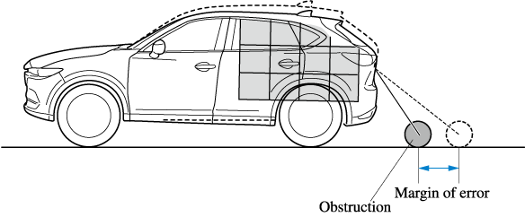
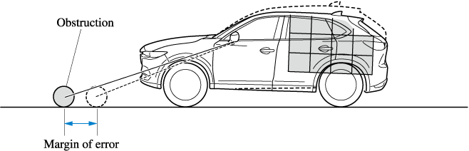
There is a steep up or down grade in the road at the front or rear of the vehicle
If there is a steep up or down grade in the road at the front or rear of the vehicle, obstructions picked up by the camera can appear farther or closer than the actual distance from the vehicle.
Front camera
Side camera
Rear camera
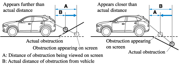
If the vehicle is on a slope, obstructions taken by the camera can appear farther or closer than the actual distance from the vehicle.
Three-dimensional object at vehicle front or rear
Because the vehicle front end guide lines (side camera) or the distance guide lines (rear camera) are displayed based on a flat surface, the distance to the three-dimensional object displayed on the screen is different from the actual distance.
Side camera

Rear camera

System Problem Indication
|
Center display indication |
Cause |
Action to be taken |
|---|---|---|
|
“No camera signal.” is displayed |
The control unit might be damaged. |
Have your vehicle inspected by an Authorized Mazda Dealer. |
|
Screen is pitch-black and blank |
The camera might be damaged. |
|
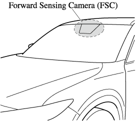
Forward Sensing Camera (FSC) (Some Models)
Your vehicle is equipped with a Forward Sensing Camera (FSC). The Forward Sensing Camera (FSC) is positioned near the rearview mirror and used by the following systems.
-
High Beam Control System (HBC)
-
Driver Attention Alert (DAA)
-
Lane-keep Assist System (LAS) & Lane Departure Warning System (LDWS)
-
Traffic Sign Recognition System (TSR)
-
Advanced Smart City Brake Support (Advanced SCBS)
-
Smart City Brake Support [Forward] (SCBS F)
-
Mazda Radar Cruise Control with Stop & Go function (MRCC with Stop & Go function)
-
Smart Brake Support (SBS)
The Forward Sensing Camera (FSC) determines the conditions ahead of the vehicle while traveling at night and detects traffic lanes. The distance in which the Forward Sensing Camera (FSC) can detect objects varies depending on the surrounding conditions.
Do not modify the suspension:
If the vehicle height or inclination is changed, the system will not be able to correctly detect vehicles ahead. This will result in the system not operating normally or mistakenly operating, which could cause a serious accident.
-
Do not apply accessories, stickers or film to the windshield near the Forward Sensing Camera (FSC).
If the area in front of the Forward Sensing Camera (FSC) lens is obstructed, it will cause the system to not operate correctly. Consequently, each system may not operate normally which could lead to an unexpected accident.
-
Do not disassemble or modify the Forward Sensing Camera (FSC).
Disassembly or modification of the Forward Sensing Camera (FSC) will cause a malfunction or mistaken operation. Consequently, each system may not operate normally which could lead to an unexpected accident.
-
Heed the following cautions to assure the correct operation of the Forward Sensing Camera (FSC).
-
Be careful not to scratch the Forward Sensing Camera (FSC) lens or allow it to get dirty.
-
Do not remove the Forward Sensing Camera (FSC) cover.
-
Do not place objects on the dashboard which reflect light.
-
Always keep the windshield glass around the camera clean by removing dirt or fogging. Use the windshield defroster to remove fogging on the windshield.
-
Consult an Authorized Mazda Dealer regarding cleaning the interior side of the windshield around the Forward Sensing Camera (FSC).
-
Consult an Authorized Mazda Dealer before performing repairs around the Forward Sensing Camera (FSC).
-
The Forward Sensing Camera (FSC) is installed to the windshield. Consult an Authorized Mazda Dealer for windshield repair and replacement.
-
When cleaning the windshield, do not allow glass cleaners or similar cleaning fluids to get on the Forward Sensing Camera (FSC) lens. In addition, do not touch the Forward Sensing Camera (FSC) lens.
-
When performing repairs around the rearview mirror, consult an Authorized Mazda Dealer.
-
Consult an Authorized Mazda Dealer regarding cleaning of the camera lens.
-
Do not hit or apply strong force to the Forward Sensing Camera (FSC) or the area around it. If the Forward Sensing Camera (FSC) is severely hit or if there are cracks or damage caused by flying gravel or debris in the area around it, stop using the following systems and consult an Authorized Mazda Dealer.
-
High Beam Control System (HBC)
-
Driver Attention Alert (DAA)
-
Lane-keep Assist System (LAS) & Lane Departure Warning System (LDWS)
-
Traffic Sign Recognition System (TSR)
-
Advanced Smart City Brake Support (Advanced SCBS)
-
Smart City Brake Support [Forward] (SCBS F)
-
Mazda Radar Cruise Control with Stop & Go function (MRCC with Stop & Go function)
-
Smart Brake Support (SBS)
-
-
The direction in which the Forward Sensing Camera (FSC) is pointed has been finely adjusted. Do not change the installation position of the Forward Sensing Camera (FSC) or remove it. Otherwise, it could result in damage or malfunction.
-
-
Always use tires for all wheels that are of the specified size, and the same manufacturer, brand, and tread pattern. In addition, do not use tires with significantly different wear patterns on the same vehicle as the system may not operate normally.
-
The Forward Sensing Camera (FSC) includes a function for detecting a soiled windshield and informing the driver, however, depending on the conditions, it may not detect plastic shopping bags, ice or snow on the windshield. In such cases, the system cannot accurately determine a vehicle ahead and may not be able to operate normally. Always drive carefully and pay attention to the road ahead.
-
In the following cases, the Forward Sensing Camera (FSC) cannot detect target objects correctly, and each system may be unable to operate normally.
-
The height of the vehicle ahead is low.
-
You drive your vehicle at the same speed as the vehicle ahead.
-
Headlights are not turned on during the night or when going through a tunnel.
-
-
In the following cases, the Forward Sensing Camera (FSC) may not be able to detect target objects correctly.
-
Under bad weather condition, such as rain, fog and snow.
-
The window washer is being used or the windshield wipers are not used when it's raining.
-
Ice, fog, snow, frost, rainfall, dirt, or foreign matter such as a plastic bag is stuck on the windshield.
-
Trucks with low loading platforms and vehicles with an extremely low or high profile.
-
When driving next to walls with no patterning (including fences and longitudinally striped walls).
-
The taillights of the vehicle ahead are turned off.
-
A vehicle is outside the illumination range of the headlights.
-
The vehicle is making a sharp turn, or ascending or descending a steep slope.
-
Entering or exiting a tunnel.
-
Heavy luggage is loaded causing the vehicle to tilt.
-
Strong light is shone at the front of the vehicle (back light or high-beam light from on-coming vehicles).
-
There are many light emitters on the vehicle ahead.
-
When the vehicle ahead is not equipped with taillights or the taillights are turned off at nighttime.
-
Elongated luggage or cargo is loaded onto installed roof rails and covers the Forward Sensing Camera (FSC).
-
Exhaust gas from the vehicle in front, sand, snow, and water vapor rising from manholes and grating, and water splashed into the air.
-
When towing a malfunctioning vehicle.
-
The vehicle is driven with tires having significantly different wear.
-
The vehicle is driven on down slopes or bumpy roads.
-
There are water puddles on the road.
-
The surroundings are dark such as during the night, early evening, or early morning, or in a tunnel or indoor parking lot.
-
The illumination brightness of the headlights is reduced or the headlight illumination is weakened due to dirt or a deviated optical axis.
-
The target object enters the blind spot of the Forward Sensing Camera (FSC).
-
A person or object bursts onto the road from the shoulder or cuts right in front of you.
-
You change lanes and approach a vehicle ahead.
-
When driving extremely close to the target object.
-
Tire chains or a temporary spare tire is installed.
-
The vehicle ahead has a special shape. For example, a vehicle towing a trailer house or a boat, or a vehicle carrier carrying a vehicle with its front pointed rearward.
-
-
If the Forward Sensing Camera (FSC) cannot operate normally due to backlight or fog, the system functions related to the Forward Sensing Camera (FSC) are temporarily stopped and the following warning lights turn on. However, this does not indicate a malfunction.
-
High Beam Control System (HBC) warning light (amber)
-
Lane-keep Assist System (LAS) & Lane Departure Warning System (LDWS) warning indication
-
Mazda Radar Cruise Control with Stop & Go function (MRCC with Stop & Go function) warning indication
-
Smart Brake Support/Smart City Brake Support (SBS/SCBS) warning indication/warning light (amber)
-
-
If the Forward Sensing Camera (FSC) cannot operate normally due to high temperatures, the system functions related to the Forward Sensing Camera (FSC) are temporarily stopped and the following warning lights turn on. However, this does not indicate a malfunction. Cool down the area around the Forward Sensing Camera (FSC) such as by turning on the air conditioner.
-
High Beam Control System (HBC) warning light (amber)
-
Lane-keep Assist System (LAS) & Lane Departure Warning System (LDWS) warning indication
-
Mazda Radar Cruise Control with Stop & Go function (MRCC with Stop & Go function) warning indication
-
Smart Brake Support/Smart City Brake Support (SBS/SCBS) warning indication/warning light (amber)
-
-
If the Forward Sensing Camera (FSC) detects that the windshield is dirty or foggy, the system functions related to the Forward Sensing Camera (FSC) are temporarily stopped and the following warning lights turn on. However, this does not indicate a problem. Remove the dirt from the windshield or press the defroster switch and defog the windshield.
-
High Beam Control System (HBC) warning light (amber)
-
Lane-keep Assist System (LAS) & Lane Departure Warning System (LDWS) warning indication
-
Mazda Radar Cruise Control with Stop & Go function (MRCC with Stop & Go function) warning indication
-
Smart Brake Support/Smart City Brake Support (SBS/SCBS) warning indication/warning light (amber)
-
-
If there are recognizable cracks or damage caused by flying gravel or debris on the windshield, always have the windshield replaced. Consult an Authorized Mazda Dealer for replacement.
-
(With Advanced Smart City Brake Support (Advanced SCBS))
-
The Forward Sensing Camera (FSC) recognizes pedestrians when all of the following conditions are met:
-
The height of a pedestrian is about 1 to 2 meters.
-
An outline such as the head, both shoulders, or the legs can be determined.
-
-
In the following cases, the Forward Sensing Camera (FSC) may not be able to detect target objects correctly:
-
Multiple pedestrians are walking, or there are groups of people.
-
A pedestrian is close to a separate object.
-
A pedestrian is crouching, lying, or slouching.
-
A pedestrian suddenly jumps into the road right in front of the vehicle.
-
A pedestrian opens an umbrella, or is carrying large baggage or articles.
-
A pedestrian is in a dark location such as during the night, or blends into the background by wearing clothes matching the background color.
-
-
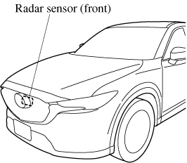
Radar Sensor (Front) (Some Models)
Your vehicle is equipped with a radar sensor (front).
The following systems also use the radar sensor (front).
-
Distance Recognition Support System (DRSS)
-
Mazda Radar Cruise Control with Stop & Go function (MRCC with Stop & Go function)
-
Smart Brake Support (SBS)
The radar sensor (front) functions by detecting the radio waves reflected off a vehicle ahead or an obstruction sent from the radar sensor.
The radar sensor (front) is mounted behind the front emblem.
If “Front Radar Sensor Blocked” is displayed in the multi-information display of the instrument cluster, clean the area around the radar sensor (front).
Heed the following precautions to assure correct operation of each system.
-
Do not adhere stickers (including transparent stickers) to the surface of the radiator grille and front emblem in and around the radar sensor (front), and do not replace the radiator grille and front emblem with any product that is not a genuine product designed for use with the radar sensor (front).
-
The radar sensor (front) includes a function for detecting soiling of the radar sensor's front surface and informing the driver, however, depending on the conditions, it may require time to detect or it may not detect plastic shopping bags, ice or snow. If this occurs, the system may not operate correctly, therefore always keep the radar sensor (front) clean.
-
Do not install a grille guard.
-
If the front part of the vehicle has been damaged in a vehicle accident, the position of the radar sensor (front) may have moved. Stop the system immediately and always have the vehicle inspected at an Authorized Mazda Dealer.
-
Do not use the front bumper to push other vehicles or obstructions such as when pulling out of a parking space. Otherwise, the radar sensor (front) could be hit and its position deviated.
-
Do not remove, disassemble, or modify the radar sensor (front).
-
For repairs, replacement or paint work around the radar sensor (front), consult an Authorized Mazda Dealer.
-
Do not modify the suspension. If the suspension are modified, the vehicle's posture could change and the radar sensor (front) may not be able to correctly detect a vehicle ahead or an obstruction.
-
Under the following conditions, the radar sensor (front) may not be able to detect vehicles ahead or obstructions correctly and each system may not operate normally.
-
The rear surface of a vehicle ahead does not reflect radio waves effectively, such as an unloaded trailer or an automobile with a loading platform covered by a soft top, vehicles with a hard plastic tailgate, and round-shaped vehicles.
-
Vehicles ahead with low vehicle height and thus less area for reflecting radio waves.
-
Visibility is reduced due to a vehicle ahead casting off water, snow, or sand from its tires and onto your windshield.
-
The luggage compartment is loaded with heavy objects or the rear passenger seats are occupied.
-
Ice, snow, or soiling is on the front surface of the front emblem.
-
During inclement weather such as rain, snow, or sand storms.
-
When driving near facilities or objects emitting strong radio waves.
-
-
Under the following conditions, the radar sensor (front) may not be able to detect vehicles ahead or obstructions.
-
The beginning and end of a curve.
-
Roads with continuous curves.
-
Narrow lane roads due to road construction or lane closures.
-
The vehicle ahead enters the radar sensor's blind spot.
-
The vehicle ahead is running abnormally due to accident or vehicle damage.
-
Roads with repeated up and down slopes
-
Driving on poor roads or unpaved roads.
-
The distance between your vehicle and the vehicle ahead is extremely short.
-
A vehicle suddenly comes close such as by cutting into the lane.
-
-
To prevent incorrect operation of the system, use tires of the same specified size, manufacturer, brand, and tread pattern on all four wheels. In addition, do not use tires with significantly different wear patterns or tire pressures on the same vehicle (Including the temporary spare tire).
-
If the battery power is weak, the system may not operate correctly.
-
When driving on roads with little traffic and few vehicles ahead or obstructions for the radar sensor (front) to detect, “Front Radar Sensor Blocked” may be temporarily displayed, however, this does not indicate a problem.
-
The radar sensors are regulated by the relevant radio wave laws of the country in which the vehicle is driven. If the vehicle is driven abroad, authorization from the country in which the vehicle is driven may be required.
Radar Sensors (Rear) (Some Models)
Your vehicle is equipped with radar sensors (rear). The following systems also use the radar sensors (rear).
-
Blind Spot Monitoring system (BSM)
-
Rear Cross Traffic Alert (RCTA)
The radar sensors (rear) function by detecting the radio waves reflected off a vehicle approaching from the rear or an obstruction sent from the radar sensor.
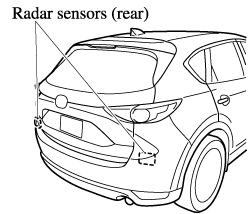
The radar sensors (rear) are installed inside the rear bumper, one each on the left and right sides.
Always keep the surface of the rear bumper near the radar sensors (rear) clean so that the radar sensors (rear) operate normally. Also, do not apply items such as stickers.
Refer to Exterior Care (Search).
If the rear bumper receives a severe impact, the system may no longer operate normally. Stop the system immediately and have the vehicle inspected at an Authorized Mazda Dealer.
-
The detection ability of the radar sensors (rear) has limitations. In the following cases, the detection ability may lower and the system may not operate normally.
-
The rear bumper near the radar sensors (rear) has become deformed.
-
Snow, ice or mud adheres to the radar sensors (rear) on the rear bumper.
-
Under bad weather conditions such as rain, snow and fog.
-
-
Under the following conditions, the radar sensors (rear) cannot detect target objects or it may be difficult to detect them.
-
Stationary objects on a road or a road side such as small, two-wheeled vehicles, bicycles, pedestrians, animals, and shopping carts.
-
Vehicle shapes which do not reflect radar waves well such as empty trailers with a low vehicle height and sports cars.
-
-
Vehicles are shipped with the direction of the radar sensors (rear) adjusted for each vehicle to a loaded vehicle condition so that the radar sensors (rear) detect approaching vehicles correctly. If the direction of the radar sensors (rear) has deviated for some reason, have the vehicle inspected at an Authorized Mazda Dealer.
-
For repairs or replacement of the radar sensors (rear), or bumper repairs, paintwork, and replacement near the radar sensors, consult an Authorized Mazda Dealer.
-
Turn off the system while pulling a trailer or while an accessory such as a bicycle carrier is installed to the rear of the vehicle. Otherwise, the radio waves emitted by the radar will be blocked causing the system to not operate normally.
-
The radar sensors are regulated by the relevant radio wave laws of the country in which the vehicle is driven. If the vehicle is driven abroad, authorization from the country in which the vehicle is driven may be required.
Ultrasonic Sensor (Rear) (Some Models)
The ultrasonic sensors (rear) function by emitting ultrasonic waves which are reflected off obstructions at the rear and the returning ultrasonic waves are picked up by the ultrasonic sensors (rear).
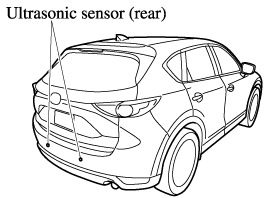
The ultrasonic sensors (rear) are mounted in the rear bumper.
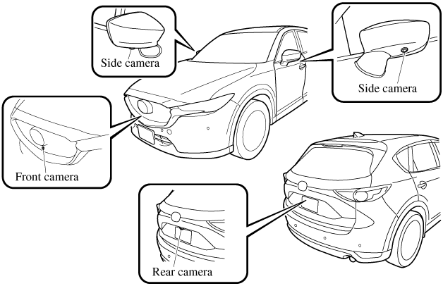
Front Camera/Side Cameras/Rear Camera (Some Models)
Your vehicle is equipped with a front camera, side cameras, and a rear camera. The 360° View Monitor uses each camera.
The front camera, side cameras, and rear camera shoot images of the area surrounding the vehicle.
Each camera is installed to the following positions.