i-ACTIVSENSE


Active Safety Technology
Active Safety Technology supports safer driving by helping the driver to recognize potential hazards and avert accidents.
Driver awareness support systems
Nighttime visibility
Left/right side and rear side detection
Road sign recognition
Inter-vehicle distance recognition
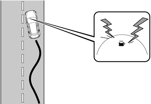
Driver fatigue detection
Rear obstruction detection when leaving a parking space
Full-surround recognition
Driver support systems
Inter-vehicle distance
Lane departure
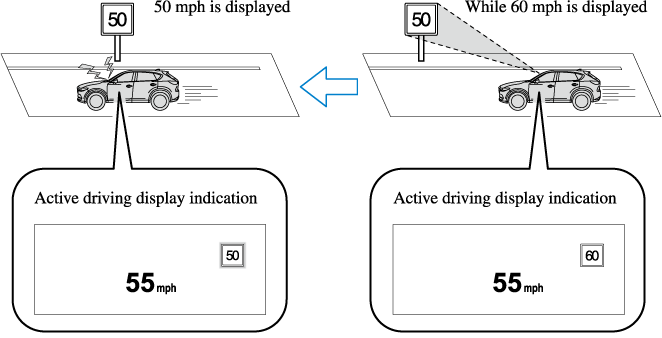
Excessive Speed Warning
If the vehicle speed exceeds the speed limit sign displayed in the active driving display, the area around the speed limit sign flashes 3 times in amber and the warning sound is activated 3 times at the same time. If the vehicle speed continues to exceed the displayed speed limit sign, the indication stops flashing and remains on. Check the surrounding conditions and adjust the vehicle speed to the legal speed using the appropriate operation such as depressing the brake pedal.
The excessive speed warning is initially set to inoperable. If you want to activate the excessive speed warning, change the setting in the personalization features. In addition, the warning pattern and the warning activation timing differ depending on the setting contents.
Refer to the Settings section in the Mazda Connect Owner's Manual.
Warning pattern
-
Off: The excessive speed warning is not activated.
-
Visual: The area around the speed limit sign displayed in the display flashes 3 times in amber, and if the vehicle speed continues to exceed the displayed speed limit sign, the indication stops flashing and remains on.
-
Audio & Visual: The area around the speed limit sign displayed in the display flashes 3 times in amber and the warning sound is activated 3 times at the same time. If the vehicle speed continues to exceed the displayed speed limit sign, the indication stops flashing and remains on.
Warning activation timing
-
 0: If the vehicle speed exceeds the speed limit sign displayed in the display, the excessive speed warning is activated.
 -
5: If the vehicle speed exceeds the speed limit sign displayed in the display by 5 km/h (3 mph), the excessive speed warning is activated.
-
10: If the vehicle speed exceeds the speed limit sign displayed in the display by 10 km/h (5 mph), the excessive speed warning is activated.
-
In the following cases, the excessive speed warning stops operating.
-
The vehicle speed is less than the speed of the displayed speed limit sign. (If the activation timing for the excessive speed warning is changed in the personalization features, the excessive speed warning stops operating when the vehicle speed is less than the changed vehicle speed.
-
A speed limit sign indication has been updated and the vehicle speed is lower than the updated indication.
-
Display of the speed limit sign stops.
-
-
The warning indication is displayed at the same time the excessive speed warning sound is activated if the vehicle speed exceeds the speed indicated on the speed limit sign.
Refer to Warning Sound is Activated (Search).
-
If the Forward Sensing Camera (FSC) incorrectly recognizes the actual speed limit sign at a lower speed, the excessive speed alarm is activated even if the vehicle is driven at the legal speed.


Driver Attention Alert (DAA) (Some Models)
The DAA is a system which detects driver fatigue and decreased attentiveness, and encourages the driver to take a rest.
When the vehicle is driven inside traffic lane lines at about 65 to 140 km/h (40 to 86 mph), the DAA estimates the amount of accumulated fatigue and decreased attentiveness of the driver based on the information from the Forward Sensing Camera (FSC) and other vehicle information, and encourages the driver to take a rest using an indication on the multi-information display and a warning sound.
Use the DAA on expressways or highways.
Refer to Forward Sensing Camera (FSC) (Search).
Do not rely completely on DAA and always drive carefully:
The DAA detects driver fatigue and decreased attentiveness and encourages the driver to take a rest, however, it is not designed to prevent the vehicle from straying. If you rely too much on the DAA it could lead to an accident. Drive carefully and operate the steering wheel appropriately.
In addition, the system may not be able to detect driver fatigue and decreased attentiveness correctly depending on the traffic and driving conditions. The driver must take sufficient rest in consideration of safer driving.
-
The DAA operates when all of the following conditions are met.
-
The vehicle speed is about 65 to 140 km/h (40 to 86 mph).
-
The system detects white (yellow) lane lines.
-
The system has completed learning of the driver’s driving data.
-
-
The DAA does not operate under the following conditions.
-
The vehicle speed is less than about 65 km/h (40 mph).
-
The vehicle speed exceeds about 140 km/h (86 mph)
-
The vehicle is making a sharp turn.
-
The vehicle is changing lanes.
-
The system cannot detect white (yellow) lane lines.
-
-
The DAA may not operate normally under the following conditions.
-
White (yellow) lane lines are less visible because of dirt or fading/patchiness.
-
The vehicle is jolted or swayed continuously by strong winds or rough roads.
-
The vehicle is driven aggressively.
-
When making frequent lane changes.
-
-
The DAA detects driver fatigue and decreased attentiveness based on the driving data when the vehicle is driven at about 65 to 140 km/h (40 to 86 mph) for about 20 minutes. The driving data will be reset under the following conditions.
-
The vehicle is stopped for 15 minutes or longer.
-
The vehicle is driven at less than about 65 km/h (40 mph) for about 30 minutes.
-
The ignition is switched off.
-
-
After the DAA has displayed the first message encouraging rest, it does not display the next one until 45 minutes have passed.
Types of Images Displayed on the Screen
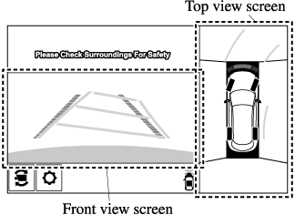
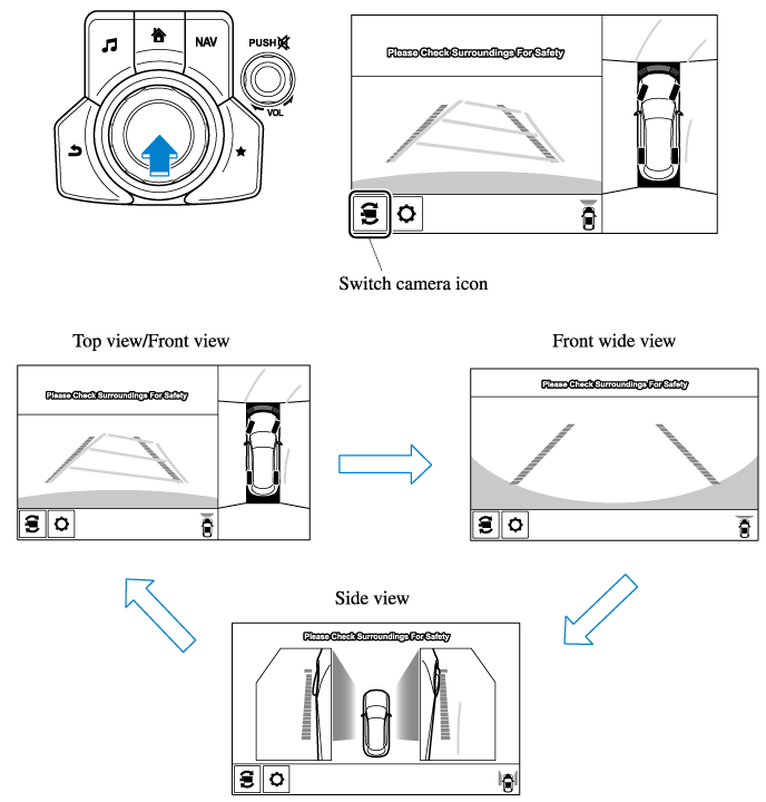
Top view/Front view
Displays the image of the area around the vehicle and the vehicle front.
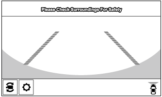
Front wide view
Displays the image of the front of the vehicle (wide-area).
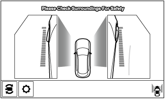
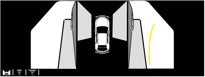
Side view
Displays the image of the left and right sides of the vehicle.
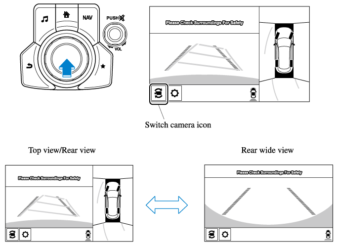
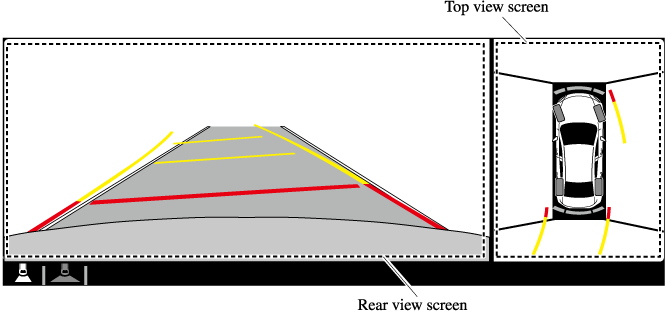
Top view/Rear view
Displays the image of the area around the vehicle and the rear of the vehicle.
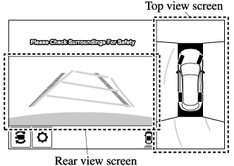
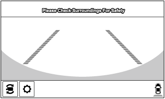
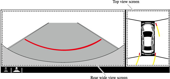
Rear wide view
Displays the image of the rear of the vehicle (wide-area).
How to Use the System
Top view/Front view, Front wide view, Side view
Indication
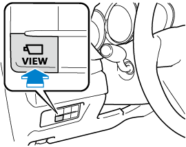
Images are displayed on the screen when the 360°View Monitor switch is pressed with all of the following conditions met.
-
The ignition is switched ON.
-
The selector lever is in a position other than R.
Display switching
You can change the displayed screen by pressing the commander knob or by touching the switch camera icon on the screen while the top view/front view, front wide view, or the side view is displayed.
-
When the selector lever is in R position, the displayed screen does not switch to the top view/front view, front wide view, or the side view.
-
Display of the top view/front view, front wide view, or the side view stops even with the display conditions met if any of the following conditions occurs.
-
When a switch around the commander knob is pressed.
-
The selector lever is shifted to P position (displayed when the selector lever is in a position other than P).
-
(Displayed when vehicle speed is less than 15 km/h (9.3 mph))
-
4 minutes and 30 seconds have passed.
-
The vehicle speed is about 15 km/h (9.3 mph) or faster.
-
-
(Displayed when the vehicle speed is about 15 km/h (9.3 mph) or faster)
-
The vehicle speed is about 15 km/h (9.3 mph) or faster after 8 seconds have passed since pressing the 360°View Monitor switch.
-
Four minutes and 22 seconds have passed from the point when the vehicle speed was less than 15 km/h (9.3 mph) after 8 seconds have passed since pressing the 360° View Monitor switch.
-
-
-
The 360°View Monitor displays the previously displayed screen.
-
The 360° View Monitor settings can be changed as follows.
Refer to the Settings section in the Mazda Connect Owner's Manual.
-
Automatic display of the 360°View Monitor when the ultrasonic senor detects an obstruction.
-
Automatic display of the 360°View Monitor when the ignition is switched ON.
-
Top view/Rear view, Rear wide view
The top view/rear view, rear wide view displays when all of the following conditions are met.
-
The ignition is switched ON.
-
Selector lever is in R position.
Display switching
The displayed screen can be switched by pressing the commander knob or by touching the switch camera icon on the screen while the top view/rear view, rear wide view is displayed.
-
The top view/rear view and rear wide view automatically display whether or not the 360° View Monitor switch is turned on or off when shifting the selector lever to R position.
-
The setting can be changed to display the top view/front view when shifting from reverse to a forward gear without operating the 360°View Monitor switch to check the front of the vehicle while parallel parking.
Refer to the Settings section in the Mazda Connect Owner's Manual.
Screen operation/icon
Always stop the vehicle when adjusting the 360°View Monitor image quality.
Do not adjust the 360°View Monitor image quality while driving. If you adjust the 360° View Monitor image quality (such as brightness, contrast, tone, and color density) while driving, it could lead to an unexpected accident.
|
Display/Icon |
Content |
|
|---|---|---|
 |
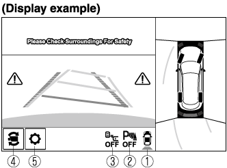
View status icon |
Indicates which image is displayed among the front view/front wide view/side view/rear view/rear wide view. |
 |
Parking sensor status icon |
Indicates that the parking sensor has a problem or it is switched off. |
 |
Rear Cross Traffic Alert (RCTA) status icon |
Indicates that the radar sensor (rear) has a problem or it is turned off. |
 |
Switch camera icon |
Each time the screen is touched, the display screen switches. |
 |
Setting icon |
The image quality for the 360°View Monitor can be adjusted. |
Types of Images Displayed on the Screen
Top view/Front view
Displays the image of the area around the vehicle and the vehicle front.
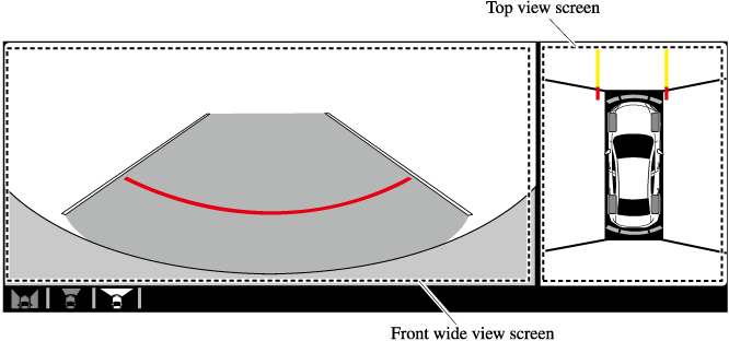
Top view/Front wide view
Displays the image of the area around the vehicle and the front of the vehicle (wide-area).
Side view
Displays the image of the left and right sides of the vehicle.
Top view/Rear view
Displays the image of the area around the vehicle and the rear of the vehicle.
Top view/Rear wide view
Displays the image of the area around the vehicle and the rear of the vehicle (wide-area).
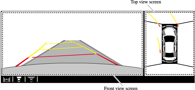
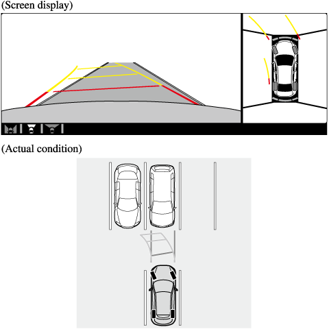
Top View/Front View
Use the top view/front view to assist in checking the safety of the surrounding area when accelerating from a stop, parking, or stopping the vehicle.
Display range
-
In the top view screen, the areas in black at the front and rear of the vehicle image and the seams where each of the camera images merge are blind spots.
-
Because images displayed in the top view screen are processed from each camera, the top view screen may display in the following ways.
-
If an image containing an object with a conspicuous color is picked up by any of the cameras, the screen area for each camera may be affected and it may display in that color.
-
Obstructions displayed in the front view may not display on the top view screen.
-
If the position or angle of each camera changes due to tilting of the vehicle, the image may appear distorted.
-
Lines on the road may appear distorted at the seams where each of the camera images merge.
-
The screen area for each camera may appear bright/dark depending on the illumination level around any of the cameras.
-
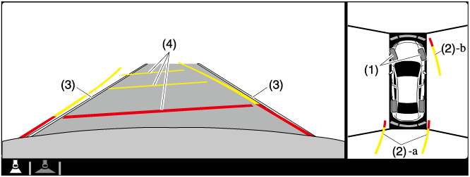
Viewing the screen
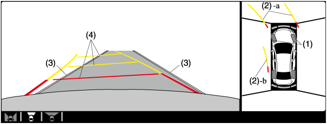
|
Display/Icon |
Content |
|
|---|---|---|
|
(1) |
Tire icon |
Indicates the tire direction. Moves in conjunction with the steering wheel operation. |
|
(2) |
Projected vehicle path lines (yellow & red) |
Indicates the approximate projected path of the vehicle. Moves in conjunction with the steering wheel operation. a) Indicates the path where the edge of the front bumper is expected to travel. b) Indicates the path where the inner side of the vehicle is expected to travel. |
|
(3) |
Extended vehicle width lines (blue) |
Indicates the approximate width of the vehicle. |
|
(4) |
Projected vehicle path distance guide lines (yellow & red) |
Indicates the distance (from front end of bumper) in front of the vehicle.
|
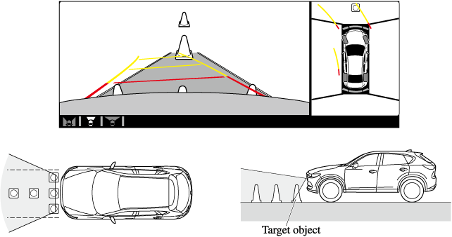
The parking sensor detection range has limitations. For example, obstructions closing in from the side and objects short in height may not be detected. Always confirm the safety around the vehicle visually when driving.
For details, refer to the parking sensor obstruction detection indication and warning sound.
Refer to Parking Sensor System (Search).
The setting can be changed so that the projected vehicle path lines are not displayed.
Refer to the Settings section in the Mazda Connect Owner's Manual.
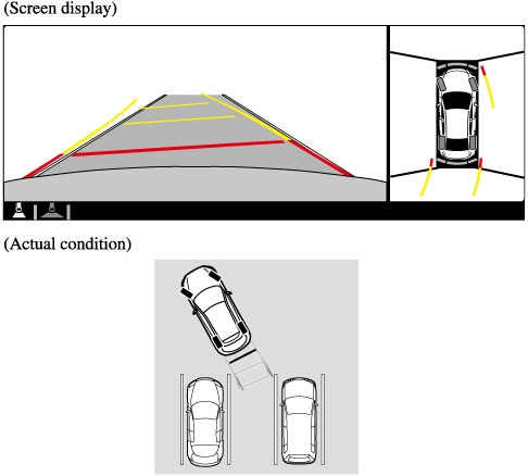
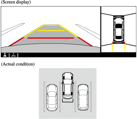
How to use the projected vehicle path line function
Make sure that there are no obstructions within the projected vehicle path lines.
Drive the vehicle forward while turning the steering wheel so that no obstructions come within the projected vehicle path lines.