


i-ACTIVSENSE
i-ACTIVSENSE
i-ACTIVSENSE is a collective term covering a series of advanced safety and driver support systems which make use of cameras and sensors. The systems consist of active safety and pre-crash safety systems.
These systems are designed to assist the driver in safer driving by reducing the load on the driver and helping to avert collisions or reduce their severity. However, because each system has its limitations, always drive carefully and do not rely solely on the systems.
Active Safety Technology
Active Safety Technology supports safer driving by helping the driver to recognize potential hazards and avert accidents.
Driver awareness support systems
Nighttime visibility
Left/right side and rear side detection
Road sign recognition
Inter-vehicle distance recognition
Front obstruction detection when approaching a crosswalk
Rear obstruction detection when leaving a parking space
Full-surround recognition
Driver fatigue detection
Driver support systems
Inter-vehicle distance
Lane departure
Lane keeping
Inter-vehicle distance and lane keeping
Pre-Crash Safety Technology
Pre-crash safety technology is designed to assist the driver in averting collisions or reducing their severity in situations where they cannot be avoided.
Collision damage reduction
Camera and Sensors
i-ACTIVSENSE uses the following detection systems.
Vehicle front

-
Forward Sensing Camera (FSC)
Refer to Forward Sensing Camera (FSC) (Search).
-
Front camera
Refer to Front Camera/Side Cameras/Rear Camera (Search).
-
Side cameras
Refer to Front Camera/Side Cameras/Rear Camera (Search).
-
Front side radar sensor
Refer to Front Side Radar Sensor (Search).
-
Front radar sensor
Refer to Front Radar Sensor (Search).
Vehicle rear

-
Rear camera
Refer to Front Camera/Side Cameras/Rear Camera (Search).
-
Rear ultrasonic sensor
Refer to Rear Ultrasonic Sensor (Search).
-
Rear side radar sensor
Refer to Rear Side Radar Sensor (Search).
Inside of vehicle

-
Driver monitoring camera
Refer to Driver Monitoring Camera (Search).
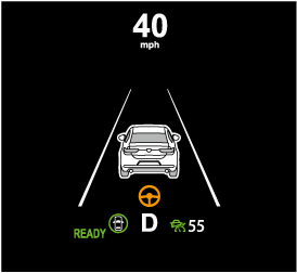
i-ACTIVSENSE Status Symbol (Warning/Risk Avoidance Support System) (Some Models)
The system notifies the driver of any of the following system status using the color or OFF indication of the i-ACTIVSENSE status symbol (Warning/risk avoidance support system).
-
Lane Departure Warning System (LDWS)
-
Blind Spot Monitoring (BSM)
-
Distance & Speed Alert (DSA)
-
Front Cross Traffic Alert (FCTA)
-
Rear Cross Traffic Alert (RCTA)
-
Lane-keep Assist System (LAS)
i-ACTIVSENSE status symbol (warning/risk avoidance support system) (white)

System stand-by status
If none of the systems are activated or if there is a problem with the system, the i-ACTIVSENSE status symbol (warning/risk avoidance support system) (white) is displayed.
For example, even when the Blind Spot Monitoring (BSM) is operating normally, if the Lane Departure Warning System (LDWS) has a problem, the i-ACTIVSENSE status symbol (warning/risk avoidance support system) (white) is displayed.


i-ACTIVSENSE status symbol (warning/risk avoidance support system) (green)

System activated status
If any one of the systems is activated, the i-ACTIVSENSE status symbol (warning/risk avoidance support system) (green) is displayed.
Even if the i-ACTIVSENSE status symbol (warning/risk avoidance support system) (green) is displayed, systems which do not meet the operation conditions will not operate.
i-ACTIVSENSE status symbol (warning/risk avoidance support system) (amber)

System warning status
If any system warning is activated, the i-ACTIVSENSE status symbol (warning/risk avoidance support system) (amber) is displayed.
i-ACTIVSENSE OFF symbol (warning/risk avoidance support system)

System OFF status
If all the systems are canceled using [Settings] in Mazda Connect or the i-ACTIVSENSE OFF switch, the i-ACTIVSENSE OFF symbol (Warning/risk avoidance support system) is displayed.
Front Radar Sensor
Your vehicle is equipped with a front radar sensor.

-
Front radar sensor
The following systems also use the front radar sensor.
-
Distance & Speed Alert (DSA)
-
Mazda Radar Cruise Control with Stop & Go function (MRCC with Stop & Go function)
-
Traffic Jam Assist (TJA)
-
Smart Brake Support (SBS) forward drive detection
The front radar sensor functions by detecting the radio waves reflected off a vehicle ahead or an obstruction sent from the radar sensor.
Heed the following precautions to assure correct operation of each system.
-
Do not apply a sticker (including a transparent one) to the front radar sensor cover or replace the front radar sensor cover with a product other than a genuine product.
-
The front radar sensor includes a function for detecting soiling of the radar sensor's front surface and informing the driver, however, depending on the conditions, it may require time to detect or it may not detect plastic shopping bags, ice or snow. If this occurs, the system may not operate correctly, therefore always keep the front radar sensor clean.
-
If “Safety and Driver Support Systems Temporarily Disabled. Front Radar Obscured. Drive Safely” is displayed on the multi-information display of the instrument cluster, clean the area around the front radar sensor.
-
Do not install a grille guard.
-
If the front part of the vehicle has been damaged in a vehicle accident, the position of the front radar sensor may have moved. Stop the system immediately and always have the vehicle inspected at an Authorized Mazda Dealer.
-
Do not use the front bumper to push other vehicles or obstructions such as when pulling out of a parking space. Otherwise, the front radar sensor could be hit and its position deviated.
-
For repairs, replacement or paint work around the front radar sensor, consult an Authorized Mazda Dealer.
-
Always use tires for all wheels that are of the specified size, and the same manufacturer, brand, and tread pattern. In addition, do not use tires with significantly different wear patterns on the same vehicle as the system may not operate normally.
-
If the lead-acid battery power is weak, the system may not operate correctly.
-
When driving on roads with little traffic and few vehicles ahead or obstructions for the front radar sensor to detect, “Safety and Driver Support Systems Temporarily Disabled. Front Radar Obscured. Drive Safely” may be temporarily displayed, however, this does not indicate a problem.
-
The radar sensors are regulated by the relevant radio wave laws of the country in which the vehicle is driven. If the vehicle is driven abroad, authorization from the country in which the vehicle is driven may be required.
When the vehicle is driven on roads in which there is an elevated road on one side, the front radar sensor function may be restricted temporarily.
When any of the following conditions is met, the front radar sensor may not be able to detect vehicles ahead or obstructions correctly and each system may not operate normally.
-
The rear surface of a vehicle ahead does not reflect radio waves effectively (such as an unloaded trailer, a vehicle with a loading platform covered by a soft top, a vehicle with a hard plastic liftgate, and a round-shaped vehicle).
-
A vehicle ahead has limited areas that can reflect radio waves (such as a low profile vehicle).
-
Under bad weather conditions (rain, fog, and snow).
-
Front visibility is reduced (due to a vehicle ahead casting off water, snow, or sand).
-
Foreign matter (ice, snow, or dirt) is on the surface of the front radar sensor cover.
-
Your vehicle is tilted (such as when heavy luggage is in the luggage compartment or on the rear seat).
-
The vehicle is driven near facilities or objects emitting strong radio waves.
When any of the following conditions is met, the front radar sensor may detect vehicles in the opposite lane or surrounding obstructions, or it may not be able to detect vehicles ahead or obstructions, and each system may not operate normally.
-
The vehicle ahead enters the front radar sensor’s blind spot.
-
The distance to the vehicle ahead is extremely close.
-
The vehicle ahead is being driven in an unstable condition.
-
A vehicle suddenly comes close such as by cutting into your lane.
-
The vehicle is entering or exiting a curve.
-
The vehicle is driven on a continuously curving road.
-
The vehicle is driven on roads with repeated up and downslopes.
-
The vehicle is driven on roads with narrow lanes.
-
The vehicle is driven on poor roads or unpaved roads.
High Beam Control System (HBC) (Some Models)
Excessive Speed Warning
If the vehicle speed exceeds the speed limit sign displayed in the active driving display/instrument cluster, the area around the speed limit sign flashes in amber and the warning sound is activated at the same time. If the vehicle speed continues to exceed the displayed speed limit sign, the indication stops flashing and remains on. Check the surrounding conditions and adjust the vehicle speed to the legal speed using the appropriate operation such as depressing the brake pedal.

-
Vehicle is doing 55 mph when 50 mph speed limit sign is recognized.
-
Vehicle continues to do 55 mph after 50 mph speed limit sign is recognized.
-
Active driving display indication
-
Instrument cluster
The excessive speed warning is initially set to inoperable. If you want to activate the excessive speed warning, change the setting in the personalization features. In addition, the warning pattern and the warning activation timing differ depending on the setting contents.
Refer to the Settings section in the Mazda Connect Owner's Manual.
Speed Limit Sign Alert setting
-
Off: The excessive speed warning is not activated.
-
Visual: The area around the speed limit sign displayed in the display flashes in amber, and if the vehicle speed continues to exceed the displayed speed limit sign, the indication stops flashing and remains on.
-
Visual + Audible: The area around the speed limit sign displayed in the display flashes in amber and the warning sound is activated at the same time. If the vehicle speed continues to exceed the displayed speed limit sign, the indication stops flashing and remains on. The warning sound is activated continuously until the vehicle speed decreases below the speed limit sign.
Speed Limit Sign Threshold setting
-
+ 0 km/h (+ 0 mph): If the vehicle speed exceeds the speed limit sign displayed in the display, the excessive speed warning is activated.
-
+ 5 km/h (+ 3 mph): If the vehicle speed exceeds the speed limit sign displayed in the display by 5 km/h (3 mph), the excessive speed warning is activated.
-
+ 10 km/h (+ 5 mph): If the vehicle speed exceeds the speed limit sign displayed in the display by 10 km/h (5 mph), the excessive speed warning is activated.
-
In the following cases, the excessive speed warning stops operating.
-
The vehicle speed is less than the speed of the displayed speed limit sign. (If the activation timing for the excessive speed warning is changed in the personalization features, the excessive speed warning stops operating when the vehicle speed is less than the changed vehicle speed.
-
A speed limit sign indication has been updated and the vehicle speed is lower than the updated indication.
-
Display of the speed limit sign stops.
-
-
The warning indication is displayed at the same time the excessive speed warning sound is activated if the vehicle speed exceeds the speed indicated on the speed limit sign.
Refer to Excessive Speed Warning (Search).
-
If the Forward Sensing Camera (FSC) or data recorded in the navigation system incorrectly recognizes the actual speed limit sign at a lower speed, the excessive speed alarm is activated even if the vehicle is driven at the legal speed.
Driver Monitoring (DM)
The DM is a system which detects driver fatigue and sleepiness, and encourages the driver to take a rest.
While driving the vehicle at about 5 km/h (3 mph) or faster, the DM detects changes in the driver's facial features using the driver monitoring camera. The system then estimates the amount of accumulated fatigue and sleepiness of the driver and encourages the driver to take a rest using a warning indication in the instrument cluster and a warning sound.
Two types of warning indication patterns are set for notifying the driver based on the estimated amount of accumulated fatigue and sleepiness of the driver.
-
Fatigue and sleepiness are detected: Warning pattern (caution)
-
Much more fatigue and sleepiness are detected: Warning pattern (warning)

Do not rely completely on the DM and always drive carefully:
The DM is a system which detects driver fatigue and sleepiness, and encourages the driver to take a rest. This is not designed to prevent driver fatigue and sleepiness, and over-reliance on the system could lead to an accident. Drive carefully and turn the steering wheel appropriately.
In addition, the system may not be able to detect driver fatigue and sleepiness correctly depending on the traffic and driving conditions. The driver must take sufficient rest in order to drive safely.
Operation conditions
The DM begins monitoring after 20 minutes have passed since the driver began driving the vehicle and when the vehicle speed is about 5 km/h (3 mph) or faster.
-
If the vehicle speed decreases to less than about 5 km/h (3 mph) while the DM is monitoring, the DM stops monitoring for 6 minutes even if the vehicle speed returns to about 5 km/h (3 mph) or faster.
-
If the driver monitoring camera does not recognize the driver correctly, the DM may not monitor correctly.
Refer to Driver Monitoring Camera (Search).
-
After the DM has displayed the first message encouraging the driver to take a rest, it does not display it again during the following periods.
-
After displaying the warning pattern (caution), the next warning pattern (caution) is not displayed until 45 minutes have passed.
-
After displaying the warning pattern (warning), the next warning pattern (warning) is not displayed until 15 minutes have passed.
-
After displaying the warning pattern (warning), the next warning pattern (caution) is not displayed until 45 minutes have passed.
-
Close Proximity Warning
If your vehicle approaches a vehicle ahead while in headway control using the Mazda Radar Cruise Control with Stop & Go function (MRCC with Stop & Go function), a warning sound is activated and a brake warning is displayed on the multi-information display. Check the surrounding conditions and keep a safe distance from the vehicle ahead.

-
“Depress Brake Pedal” message is displayed
-
While the accelerator pedal is being depressed, the warnings and brake control do not operate even if your vehicle approaches the vehicle ahead.
-
In the following cases, the warnings and brakes may not operate even if your vehicle approaches the vehicle ahead.
-
Your vehicle is being driven at the same speed as the vehicle ahead.
-
Immediately after the MRCC with Stop & Go function is set.
-
Immediately after the accelerator pedal is released.
-
Another vehicle cuts into the driving lane.
-
Setting the System
Operation switch

-
CANCEL switch
-
RES switch
-
MRCC switch
Operation conditions
The MRCC with Stop & Go function operates when all of the following conditions are met.
-
The MRCC with Stop & Go function is on.
-
The selector lever is in the D position.
-
The parking brake is released.
-
All the doors are closed.
-
The driver's seat belt is fastened.
-
Vehicle speed is 0 to 140 km/h (0 to 87 mph)
-
In the following cases, the MRCC with Stop & Go function system is canceled when the vehicle is traveling at 30 km/h (20 mph) or less and “Mazda Radar Cruise Control Disabled Under 30 km/h” is displayed in the multi-information display.
-
The Forward Sensing Camera (FSC) cannot detect target objects.
-
There is a problem with the stop hold control function.
-
There is a problem with the Electric Parking Brake (EPB).
-
Setting the vehicle speed
-
Press the MRCC switch to turn the system on.
-
Accelerate the vehicle until it reaches the desired speed using the accelerator pedal and press the RES switch up (SET+) or down (SET-) to set the speed.
-
When the system is turned on, the MRCC standby indication (white) turns on and the MRCC display indications are displayed on the multi-information display and the active driving display.
-
When the vehicle speed is set, the set vehicle speed is displayed on the displays and the MRCC standby indication (white) changes to the MRCC set indication (green).
-
The minimum speed setting is 30 km/h (19 mph).
|
Travel status |
Indication on multi-information display |
Indication on active driving display |
|---|---|---|
|
During travel at constant speed |
 |
 |
|
During travel under headway control |
 |
 |
Setting the distance between vehicles
The distance between vehicles is set to a shorter distance by pressing the CANCEL switch down, and to a longer distance by pressing the CANCEL switch up. The distance between vehicles can be set to 4 levels: Long, medium, short, and extremely short distance.
The distance between vehicles increases or decreases depending on the vehicle speed.
|
Distance-between-vehicles guideline (at 80 km/h (50 mph) vehicle speed) |
Indication on multi-information display |
Indication on active driving display*1 |
|---|---|---|
|
Long (about 50 m (164 ft)) |
 |
 |
|
Medium (about 40 m (131 ft)) |
 |
 |
|
Short (about 30 m (98 ft)) |
 |
 |
|
Extremely short (about 25 m (82 ft)) |
 |
 |
-
Displays a pop-up image in the active driving display only when the driver operates the switch.
Changing the set vehicle speed
How to change the set vehicle speed using the RES switch
When the RES switch is pressed up (SET+), the vehicle accelerates, and when the RES switch is pressed down (SET-), the vehicle decelerates.
-
Press and release immediately: 1 km/h (1 mph)
-
Press and hold: 10 km/h (5 mph)
How to change the set vehicle speed using the accelerator pedal
Depress the accelerator pedal until the vehicle speed reaches the desired speed, then press the RES switch up (SET+) or down (SET-) and release the switch.
Temporary cancellation
If any of the following conditions is met, the MRCC with Stop & Go function is canceled temporarily.
-
The MRCC with Stop & Go function operation conditions are not met.
-
The CANCEL switch is pressed.
-
The brake pedal is depressed.
-
The front radar sensors cannot detect target objects.
-
The DSC has operated.
-
The Smart Brake Support (SBS) has operated.
-
The frequency of the braking operation by the MRCC with Stop & Go function is high.
-
There is a problem in the system.
Resuming the control
If the MRCC with Stop & Go function is temporarily canceled, it will resume operation at the previously set speed by pressing the RES switch after all of the operation conditions have been met again.
Turning off the system
When the MRCC switch is pressed while the MRCC is operating, the MRCC turns off.
System Canceling
The Lane-keep Assist System (LAS) can be set to inoperable.
-
(If only the LAS is turned off)
Refer to the Settings section in the Mazda Connect Owner's Manual.
-
(If the LAS is turned off by operating the i-ACTIVSENSE OFF switch)
Refer to i-ACTIVSENSE OFF Switch (Search).
If the power switch is switched OFF while you have canceled the system using the i-ACTIVSENSE OFF switch, the LAS is automatically enabled the next time the power switch is switched ON. However, if the system is canceled using [Settings] in Mazda Connect, the LAS is not automatically enabled.
Emergency Lane Keeping (ELK) (Some Models)
Emergency Lane Keeping (ELK)
The ELK is a system designed to assist the driver’s steering wheel operation to avoid danger.
The ELK consists of the Blind Spot Assist function to prevent your vehicle from colliding with vehicles on adjacent lanes, and the Road Keep Assist function to prevent your vehicle from deviating from the road.
Refer to Blind Spot Assist (Search).
Refer to Road Keep Assist (Search).
Blind Spot Assist (Some Models)
The Blind Spot Assist function assists the driver in avoiding collisions with vehicles in adjacent lanes (excluding vehicles approaching in the opposite direction).
The Blind Spot Assist function detects white lines (yellow lines) on the vehicle lane using the Forward Sensing Camera (FSC) and detects vehicles on adjacent lanes using the rear side radar sensors. If there is a possibility of a collision with a vehicle in an adjacent lane when you try to change lanes or if you may deviate from your lane, it assists your steering wheel operation to keep you in the driving lane.
When the steering wheel operation assist operates, a warning sound and warning indications on displays alert the driver of the possibility of a collision. Furthermore, if the possibility of a collision increases, a warning sound and display indications alert the driver of the danger.

Do not rely completely on the Blind Spot Assist function and always drive carefully:
-
The Blind Spot Assist function has limitations. Do not rely completely on the system and always stay on course using the steering wheel.
-
The Blind Spot Assist function is not an autonomous driving system. In addition, the system is not designed to compensate for a driver’s lack of caution, and over-reliance on the system could lead to an accident.
-
The detection area of the camera and sensors is limited. If the steering wheel operation assist is operated without detecting a two-wheeled vehicle near the detecting vehicle, it could result in an accident.

Do not use the system under the following conditions. Otherwise, it may result in an accident:
-
The vehicle is driven on slippery roads such as icy roads, snow-covered roads, and unpaved roads.
-
Tires other than the specified size are used, such as when tire chains or temporary spare tires are used.
-
The vehicle is towing a camping trailer or boat trailer.
-
The vehicle is driven on roads other than expressways and highways.
-
The rear bumper around a rear side radar sensor is deformed.
Operation conditions
The Blind Spot Assist function becomes operational when all of the following conditions are met.
-
The vehicle speed is about 64 km/h (40 mph) or faster.
-
The vehicle is driven on a straight road or gentle curve.
-
The system detects white (yellow) lane lines on both sides.
-
There is a vehicle on the rear sides.
-
The Blind Spot Assist function may not operate normally when any of the following conditions is met.
-
A condition under which the Forward Sensing Camera (FSC) cannot detect a target object is met.
Refer to Forward Sensing Camera (FSC) (Search).
-
The visibility of vehicles in adjacent lanes is poor.
-
A vehicle in an adjacent lane rapidly approaches at a high speed.
-
Vehicles in adjacent lanes have any of the following shapes.
-
The vehicle size is very small.
-
The vehicle height is extremely low or high.
-
A special type of vehicle with a complex shape.
-
-
The visibility of white lines (yellow lines) is poor (due to paint flaking or dirt, or being hidden by vehicles ahead).
-
There are multiple white lines (yellow lines) or they are interrupted.
-
A misleading line on the road is picked up (such as temporary line for construction, shadow, lingering snow, or grooves filled with water).
-
The width of the vehicle lane is narrow or wide.
-
The vehicle is shaken after hitting a road bump.
-
The vehicle is driven on a section with a closed lane or temporary lane due to construction.
-
The vehicle is driven on a forked road or junction.
-
-
When the ELK OFF indicator light is on, the system is canceled according to a Mazda Connect setting.
Refer to the Settings section in the Mazda Connect Owner's Manual.

Temporary cancellation of the function
The Blind Spot Assist function goes on stand-by when any of the following conditions is met. The Blind Spot Assist function is automatically restored when its operation conditions are met.
-
The vehicle speed is less than about 56 km/h (35 mph).
-
The system cannot detect white (yellow) lane lines.
-
The accelerator pedal is depressed abruptly.
-
The brake pedal is depressed.
-
The steering wheel is operated abruptly.
-
The TCS/DSC is operating.
-
The TCS/DSC is turned off.
-
Multiple vehicles are traveling in the detecting area near your vehicle.
Cancellation of the function
The Blind Spot Assist function is canceled when any of the following conditions is met.
-
The temperature in the Forward Sensing Camera (FSC) is high or low.
-
The windshield around the Forward Sensing Camera (FSC) is foggy.
-
The windshield around the Forward Sensing Camera (FSC) is blocked by an obstruction, causing poor forward visibility.
-
Snow, ice, or mud is adhering around a rear side radar sensor.
-
The temperature around a rear side radar sensor is high.
-
There is a problem with the system.
System problem
If there is a problem with the system, the i-ACTIVSENSE warning indication/warning light turns on and a message is indicated.
Refer to i-ACTIVSENSE Warning Indication/Warning Light (Search).
Steering wheel operation assist
If there is a possibility of collision with a vehicle in an adjacent lane when you try to change lanes or if you may deviate from the lane, the steering wheel operation assist operates.
While the steering wheel operation assist is operating, the system notifies the driver using a warning sound, multi-information display, and the active driving display that it is assisting the steering wheel operation.
Multi-information display (Basic display)

Multi-information display (i-ACTIVSENSE display)
Active driving display

-
If the driver operates the steering wheel while the steering wheel operation assist is operating, the steering wheel operation assist is canceled.
-
When the steering wheel operation assist is performed several times within a certain period of time, the warning sound is activated.
Collision warning
If the possibility of a collision with a vehicle in an adjacent lane increases, the direction to which the steering wheel needs to be turned to avoid a collision is displayed on the multi-information display and the active driving display, together with a warning sound activated.
Multi-information display

Active driving display

Road Keep Assist

Stopping the Emergency Lane Keeping (ELK) System Operation
The ELK can be set to inoperable.
Refer to the Settings section in the Mazda Connect Owner's Manual.
When the ELK is canceled, the ELK OFF indicator light turns on.
Reverse drive detection (Some Models)
When you are driving in reverse, the following functions of the Smart Brake Support (SBS) operate.
-
Rearward detection function
-
Rear crossing
Do not rely completely on the SBS:
The SBS is only designed to reduce damage in the event of a collision. Over reliance on the system leading to the accelerator pedal or brake pedal being mistakenly operated could result in an accident.
Heed the following cautions so that the SBS can operate normally:
-
Do not apply stickers (including transparent stickers) to the areas around the rear side radar sensors and the rear ultrasonic sensors. Otherwise, a rear side radar sensor and a rear ultrasonic sensor may not be able to detect vehicles and obstructions correctly which could result in an accident.
-
Do not disassemble the rear side radar sensors and rear ultrasonic sensors.
-
If you recognize scratches around the rear side radar sensors and rear ultrasonic sensors, stop using the SBS immediately and always have the vehicle inspected by an Authorized Mazda Dealer.
Refer to Stopping the Smart Brake Support (SBS) System Operation (Search).
-
Consult an Authorized Mazda Dealer for rear bumper removal/installation.
Do not modify the suspension:
If the vehicle height or inclination is changed, the SBS may not operate correctly because it cannot detect obstructions correctly.
Do not hit the rear side radar sensors and rear ultrasonic sensors forcefully:
When washing the vehicle, do not spray highly pressurized water against the rear side radar sensors and the rear ultrasonic sensors, or rub them strongly. In addition, do not hit the rear bumper forcefully when loading and unloading cargo. Otherwise, the system will be unable to detect obstructions correctly and the SBS may not operate normally.
-
In the following cases, turn the SBS off to prevent a mis-operation.
-
A trailer is pulled or an accessory such as a bicycle carrier is installed to the rear of the vehicle.
-
The vehicle is driven on rough roads such as in areas where there is grass and foliage or off-road.
Refer to Stopping the Smart Brake Support (SBS) System Operation (Search).
-
-
Always use tires for all wheels that are of the specified size, and the same manufacture, brand, and tread pattern. In addition, do not use tires with significantly different wear patterns on the same vehicle. If such improper tires are used, the SBS may not operate normally.
During the SBS brake control, the brake pedal may move rearward or become stiff. The brakes are operating, but continue to depress the brake pedal.
Rearward detection function
The rearward detection function is designed to reduce damage in the event of a collision with a target object when reversing.
The rearward detection function detects obstructions using the rear ultrasonic sensors. In addition, if there is the possibility of your vehicle colliding with a target object at the rear while you are driving in reverse, you are notified of possible danger by a warning sound and a warning indication on the display.
Furthermore, if the possibility of a collision increases, brake control is performed to reduce damage in the event of a collision.

Always check the surrounding area visually when reversing the vehicle:
The operation of the rearward detection function has certain limitations. Therefore, the function might not operate or it might be delayed even if there is a target object at the rear of your vehicle. Always make it your responsibility as a driver to check the rear.
Operation conditions
The rearward detection function operates when all of the following conditions are met.
-
The EV system is operating.
-
The SBS is on.
-
The selector lever is in the R position.
-
The vehicle speed is about 2 km/h (2 mph) to 8 km/h (4 mph).
-
There is no problem with the DSC.
-
The Electric Parking Brake (EPB) is not operating.
-
When any of the following conditions is met, the rearward detection function may not operate.
-
Directly after the EV system starts.
-
The height of the obstruction is low such as low walls or trucks with low loading platforms.
-
The height of the obstruction is high such as trucks with high loading platforms.
-
The obstruction is not as large as a vehicle or wall.
-
The obstruction is thin such as a signpost.
-
The surface of the obstruction is not pointed vertically relative to your vehicle.
-
The obstruction is soft such as a hanging curtain or snow stuck to a vehicle.
-
The obstruction is shaped irregularly.
-
The obstruction is extremely close.
-
-
When any of the following conditions is met, the rearward detection function may not operate normally.
-
Snow, ice, or mud adheres to the area around a rear ultrasonic sensor.
-
The vehicle posture is unstable due to sudden operation of the steering wheel, accelerator pedal, or brake pedal.
-
There is another obstruction near one obstruction.
-
During inclement weather such as rain, fog, and snow.
-
High or low humidity.
-
High or low temperatures.
-
Strong winds.
-
The path of travel is not flat.
-
Heavy luggage is loaded in the luggage compartment or on the rear seat and the vehicle is tilted.
-
Objects such as a wireless antenna, fog light, or illuminated license plate is installed near a rear ultrasonic sensor.
-
The orientation of a rear ultrasonic sensor has deviated for reasons such as a collision.
-
The vehicle is affected by other sound waves such as the horn, engine noise, or rear ultrasonic sensor of another vehicle.
-
-
When any of the following conditions is met, the rearward detection function may operate.
-
Reversing towards a steep ascending slope.
-
There are grating, wheel blocks, a road curb, or a bump.
-
There is a hanging curtain or railroad crossing gate.
-
Reversing near objects such as foliage, barriers, vehicles, walls, or fences.
-
The vehicle is driven on rough roads such as in areas where there is grass and foliage or off-road.
-
When reversing through low gates, narrow gates, car washing machines, tunnels, or into a mechanical parking garage.
-
A towing bar is installed or a trailer is connected.
-
-
If the system performs brake control and the vehicle is stopped, the system will continue to hold the brakes for a brief time unless there is an operation performed by the driver.
Collision warning
If there is the possibility of your vehicle colliding with a vehicle approaching from the rear on the left or right, or from the rear while you are driving in reverse, a warning sound is activated continuously and a warning is displayed on the multi-information display and the active driving display.
Multi-information display

-
“BRAKE!” message is displayed
Active driving display

-
“BRAKE!” message is displayed
Rear crossing
The Rear Crossing detection function is designed to reduce the damage in the event of a collision with a vehicle approaching from the rear sides while driving in reverse.
The Rear Crossing detection function detects approaching vehicles using the rear side radar sensors. If there is the possibility of your vehicle colliding with a vehicle approaching from the rear sides while you are driving in reverse, you are notified of possible danger by a warning sound and a warning indication on the display.
Furthermore, if the possibility of a collision increases, brake control is performed to reduce damage in the event of a collision.

Always check the surrounding area visually when reversing the vehicle:
The operation of the Rear Crossing detection function has certain limitations. Therefore, the function might not operate or it might be delayed even if there is a vehicle passing through the rear of your vehicle. Always make it your responsibility as a driver to check the rear.
Do not rely completely on the Rear Crossing detection function:
The Rear Crossing detection function operates on vehicles while you are driving in reverse. It will not operate on walls, pedestrians, or animals.
Operation conditions
The Rear Crossing detection function operates when all of the following conditions are met.
-
The EV system is operating.
-
The SBS is on.
-
The selector lever is in the R position.
-
The vehicle speed is about 10 km/h (6.2 mph) or slower.
-
The vehicle speed of an approaching vehicle is about 3 km/h (2 mph) or faster.
-
There is no problem with the DSC.
-
When any of the following conditions is met, the i-ACTIVSENSE warning indication/warning light is turned on and the system operation is stopped. If the i-ACTIVSENSE warning indication/warning light remains on, have the vehicle inspected by an Authorized Mazda Dealer as soon as possible.
-
There is a problem with the system.
-
A large deviation in the installation position of a rear side radar sensor on the vehicle has occurred.
-
Snow, ice, or mud is adhering around a rear side radar sensor.
-
The temperature around a rear side radar sensor is high.
-
Driving on snow-covered roads for long periods.
-
The lead-acid battery voltage has decreased.
-
-
When any of the following conditions is met, the Rear Crossing detection function will not detect approaching vehicles or they may be difficult to detect.
-
The rear side radar sensor detection area is obstructed by a nearby wall or parked vehicle. (Reverse the vehicle to a position where the radar sensor detection area is no longer obstructed.)

-
Your vehicle
-
-
A vehicle is approaching directly from the rear of your vehicle.

-
Your vehicle
-
-
The vehicle is parked on a slant.

-
Your vehicle
-
-
A vehicle is approaching from the opposite direction on a steep gradient.

-
Your vehicle
-
-
Directly after the EV system starts.
-
Just after the SBS operation has been enabled using [Settings] in Mazda Connect.
-
Radio wave interference from a radar sensor equipped on a vehicle parked nearby.
-
-
When any of the following conditions is met, the Rear Crossing may operate.
-
There is a hanging curtain or railroad crossing gate.
-
Reversing near objects such as foliage, barriers, vehicles, walls, or fences.
-
The vehicle is driven on rough roads such as in areas where there is grass and foliage or off-road.
-
When reversing through low gates, narrow gates, car washing machines, or tunnels.
-
A towing bar is installed or a trailer is connected.
-
-
If the system performs brake control and the vehicle is stopped, the system will continue to hold the brakes for a brief time unless there is an operation performed by the driver.
Collision warning
If there is the possibility of your vehicle colliding with a vehicle approaching from the rear on the left or right, or from the rear while you are driving in reverse, a warning sound is activated continuously and a warning is displayed on the multi-information display and the active driving display.
Multi-information display
-
“BRAKE!” message is displayed
Active driving display
-
“BRAKE!” message is displayed
Top View/Front View
Use the top view/front view to assist in checking the safety of the surrounding area when accelerating from a stop, parking, or stopping the vehicle.
Display range

-
Target object
-
In the top view screen, the areas in black at the front and rear of the vehicle image and the seams where each of the camera images merge are blind spots.
-
Because images displayed in the top view screen are processed from each camera, the top view screen may display in the following ways.
-
Depending on the surrounding environment, the color of objects may be displayed on the screen in a color different from the actual one.
-
Depending on the surrounding environment, it may take a few seconds for the color of the screen display to adjust.
-
Obstructions displayed in the front view may not display on the top view screen.
-
If the position or angle of each camera changes due to tilting of the vehicle, the image may appear distorted.
-
Lines on the road may appear distorted at the seams where each of the camera images merge.
-
The screen area for each camera may appear bright/dark depending on the illumination level around any of the cameras.
-
Viewing the screen

|
Display/Icon |
Content |
|
|---|---|---|
|
(1) |
Tire icon |
Indicates the tire direction. Moves in conjunction with the steering wheel operation. |
|
(2) |
Projected vehicle path lines (yellow & red) |
Indicates the approximate projected path of the vehicle. Moves in conjunction with the steering wheel operation. a) Indicates the path where the edge of the front bumper is expected to travel. b) Indicates the path where the inner side of the vehicle is expected to travel. |
|
(3) |
Extended vehicle width lines (blue) |
Indicates the approximate width of the vehicle. |
|
(4) |
Projected vehicle path distance guide lines (yellow & red) |
Indicates the distance (from front end of bumper) in front of the vehicle.
|
The parking sensor detection range has limitations. For example, obstructions closing in from the side and objects short in height may not be detected. Always confirm the safety around the vehicle visually when driving.
For details, refer to the parking sensor obstruction detection indication and warning sound.
Refer to Parking Sensor System (Search).
The setting can be changed so that the projected vehicle path lines are not displayed.
Refer to the Settings section in the Mazda Connect Owner's Manual.
How to use the projected vehicle path line function

-
(Screen display)
-
(Actual condition)
Make sure that there are no obstructions within the projected vehicle path lines.
Drive the vehicle forward while turning the steering wheel so that no obstructions come within the projected vehicle path lines.
Top View/Front Wide View

Use the top view/front wide view to assist in checking the safety of the surrounding area when accelerating from a stop or entering a T-shaped intersection and intersection.
Display range

-
Target object
-
In the top view screen, the areas in black at the front and rear of the vehicle image and the seams where each of the camera images merge are blind spots.
-
Because images displayed in the top view screen are processed from each camera, the top view screen may display in the following ways.
-
Depending on the surrounding environment, the color of objects may be displayed on the screen in a color different from the actual one.
-
Depending on the surrounding environment, it may take a few seconds for the color of the screen display to adjust.
-
Obstructions displayed in the front view may not display on the top view screen.
-
If the position or angle of each camera changes due to tilting of the vehicle, the image may appear distorted.
-
Lines on the road may appear distorted at the seams where each of the camera images merge.
-
The screen area for each camera may appear bright/dark depending on the illumination level around any of the cameras.
-
Viewing the screen

|
Display/Icon |
Content |
|
|---|---|---|
|
(1) |
Extended vehicle width lines and distance guide lines (blue & red) |
Indicates the approximate width of the vehicle and the distance (from front end of bumper) in front of the vehicle.
|
The front wide view screen displays the image in front of the vehicle at a wide angle and corrects the image to help detect approaching obstructions from the side. Therefore, it differs from the actual view.
Side View
Use the side view to assist in checking the safety of the surrounding area when accelerating from a stop, parking, or stopping the vehicle.
Display range

-
Target object
Viewing the screen

|
Display/Icon |
Content |
|
|---|---|---|
|
(1) |
Projected vehicle path lines (yellow) |
Indicates the approximate projected path of the vehicle. Moves in conjunction with the steering wheel operation. The projected vehicle path lines (yellow) indicate the path the inner side of the vehicle is expected to travel. |
|
(2) |
Vehicle parallel guide lines (blue) |
Indicates the approximate vehicle width including the door mirrors. |
|
(3) |
Vehicle front end guide lines (blue) |
Indicates the point about 0.25 m (9.84 in) from the front edge of the vehicle (front edge of the bumper). |
The setting can be changed so that the projected vehicle path lines are not displayed.
Refer to the Settings section in the Mazda Connect Owner's Manual.
How to use the projected vehicle path line function

-
(Screen display)
-
(Actual condition)
Make sure that there are no obstructions within the projected vehicle path lines.
Turn the steering wheel so that the projected vehicle path lines travel inside of the obstruction (A), and drive the vehicle forward until it passes the obstruction.
If the projected vehicle path lines are on an obstruction (B) or outside of the obstruction (C), the vehicle may contact the obstruction when turning the vehicle sharply.
-
The parking sensor detection range has limitations. For example, obstructions closing in from the side and objects short in height may not be detected. Always confirm the safety around the vehicle visually when driving.
For details, refer to the parking sensor obstruction detection indication and warning sound.
Refer to Parking Sensor System (Search).
-
Do not turn the steering wheel any more until the vehicle has passed the obstruction, even if the obstruction is not visible on the side view image. If the steering wheel is turned even more, the vehicle may contact the obstruction if it is turned sharply.
-
Because there might be a difference between the image displayed on the screen and the actual conditions, always check the safety of the surrounding area using the mirrors and directly with your eyes when driving.
-
Even though the object displayed on the screen, such as a road curb or a division line of a parking space, and the vehicle parallel guide lines appear parallel, they may not actually be parallel.
Top View/Rear View
Use the top view/rear view to assist in checking the safety of the surrounding area when accelerating from a stop, parking, or stopping the vehicle.
Range of displayed screen image

-
Target object
-
In the top view screen, the areas in black at the front and rear of the vehicle image and the seams where each of the camera images merge are blind spots.
-
Because images displayed in the top view screen are processed from each camera, the top view screen may display in the following ways.
-
Depending on the surrounding environment, the color of objects may be displayed on the screen in a color different from the actual one.
-
Depending on the surrounding environment, it may take a few seconds for the color of the screen display to adjust.
-
Obstructions displayed in the rear view may not display on the top view screen.
-
If the position or angle of each camera changes due to tilting of the vehicle, the image may appear distorted.
-
Lines on the road may appear distorted at the seams where each of the camera images merge.
-
The screen area for each camera may appear bright/dark depending on the illumination level around any of the cameras.
-
Viewing the screen

|
Display/Icon |
Content |
|
|---|---|---|
|
(1) |
Tire icon |
Indicates the tire direction. Moves in conjunction with the steering wheel operation. |
|
(2) |
Projected vehicle path lines (yellow & red) |
Indicates the approximate projected path of the vehicle. Moves in conjunction with the steering wheel operation. a) Indicates the path where the edge of the rear bumper is expected to travel. b) Indicates the path where the outer side of the vehicle is expected to travel. |
|
(3) |
Extended vehicle width lines (blue) |
These guide lines indicate the approximate width of the vehicle. |
|
(4) |
Projected vehicle path distance guide lines (yellow & red) |
These guide lines indicate the approximate distance to a point measured from the rear of the vehicle (from the end of the bumper).
|
The setting can be changed so that the projected vehicle path lines are not displayed.
Refer to the Settings section in the Mazda Connect Owner's Manual.
How to use the projected vehicle path line function
-
The front of the vehicle swings out wide when turning the steering wheel while reversing. Maintain sufficient distance between the vehicle and an obstruction.
-
The parking sensor detection range has limitations. For example, obstructions closing in from the side and objects short in height may not be detected. Always confirm the safety around the vehicle visually when driving.
For details, refer to the parking sensor obstruction detection indication and warning sound.
Refer to Parking Sensor System (Search).
-
Because there might be a difference between the image displayed on the screen, such as indicated in the following, and the actual conditions when parking, always check the safety at the rear of the vehicle and the surrounding area directly with your eyes.
-
Even though the back end of the parking space (or garage) displayed on the screen and distance guide lines appear parallel, they may not actually be parallel.
-
When parking in a space with a division line on only one side of the parking space, even though the division line and the vehicle width guide line appear parallel, they may not actually be parallel.
-
-
The following shows an example of vehicle parking with the steering wheel turned to the left while backing up the vehicle. When backing into a parking space from the opposite direction, the steering operation is reversed.
-
Back the vehicle into the parking space by turning the steering wheel so that the vehicle enters the center of the parking space.

-
(Screen display)
-
(Actual condition)
-
-
After the vehicle starts entering the parking space, stop and adjust the steering wheel so that the distance between the vehicle width lines and the sides of the parking space on the left and right are roughly equal, and then continue backing up slowly.
-
Once the vehicle width lines and the sides of the parking space on the left and right are parallel, straighten the wheels and back the vehicle slowly into the parking space. Continue checking the vehicle's surroundings and then stop the vehicle in the best possible position. (If the parking space has division lines, check whether the vehicle width guide lines are parallel to them.)

-
(Screen display)
-
(Actual condition)
-
System Problem Indication
|
Center display indication |
Cause |
Action to be taken |
|---|---|---|
|
“No camera signal.” is displayed |
The control unit might be damaged. |
Have your vehicle inspected by an Authorized Mazda Dealer. |
|
Screen is pitch-black and blank |
The camera might be damaged. |
|
